Kliche Mini worked... and now no sound?

dangosp

New member
Hello,
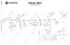
I recently built the Kliche Mini, assembled in the enclosure, and got it working perfectly, which I was very happy with as a first build. Maybe the 4th or 5th time I played it, all of a sudden I have no sound both bypass or turned on. I read through some past forum questions to try and get a handle on this myself, resoldered around the IC holders, studied the schematics as best I could understand them, built an audio probe, and now I'm stuck!
The circuit turns on, led lights up, no sound at all. Testing with the audio probe, I can get audio From In, R1, C1, and pin 3 of IC1, where there it dies. Not sure its relevant, but I tried swapping the TL072 IC's (IC1 and IC2) and then I get no audio out from C1.
I measured the DC on both TL072's and the TC1044SCPA and got the following:
IC1-
1- 3.4
2- 3.4
3- 7.3
4- 0
5- 8
6- 8
7-8.6
8- 9.1
IC2-
1-7.7
2- 7.7
3-8
4-8
5- 8
6-8
7- 7.9
8-8.3
IC3-
1- 9.1
2- 9.1
3- 0
4 - 9.1
5- 8
6-8.6
7- 8.6
8- 9.1

Sorry for the long winded post, I was so excited that I got this pedal working right out the gate, it sounded incredible with my bassman...and then not!
Thanks in advance....
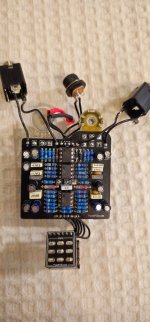
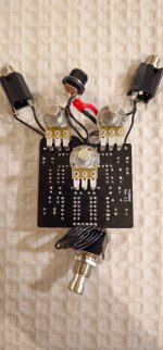
Photos incoming....
 
Crazy question, so you have the audio cables plugged in right? In and out, etc. it may sound silly, but you will come to find out, it happens to all of us. Sometimes, I plug in the wrong cables entirely. Been doing this for over 10 years if that helps to put perspective on it.
 
Crazy question, so you have the audio cables plugged in right? In and out, etc. it may sound silly, but you will come to find out, it happens to all of us. Sometimes, I plug in the wrong cables entirely. Been doing this for over 10 years if that helps to put perspective on it.
I appreciate your experience. I have done the same. I did verify the cables were correctly placed, and was able to get audio out with the audio probe with limits.
 
I think something's gone quite wrong in your power section, but it can be hard to tell for sure with the op-amps in there.
What do the voltages measure at the pins with IC1 and IC2 removed?

It's not clear when you list your voltages since you're using a dash to separate the pin number from the
voltage -- is that a separator or a negative voltage?

You might have something shorted if you have 8V on pin 4 of IC2. I think that should be -9V and pin 8 should
be ~17.something volts.

Things look kind of weird/crusty on the right-hand pins of your charge pump. Stray solder or bits of stranded
wire or bellybutton lint or something? Maybe a short up in there.
Thanks for the response. All those were positive voltage readings when powered on, sorry about the confusing format.
I removed IC1 and IC2, new readings:
IC1-
1. 4.6
2. 4.6
3. 4.2
4. 0
5. 4.5
6. 4.5
7. 4.5
8. 9.1
IC2-
1. 4.5
2. 4.5
3. 4.5
4. 8.3
5. 4.6
6. 4.6
7. 4.5
8. 8.6
IC3-
1. 9.1
2. 9.1
3. 0
4. 9.1
5. 8.3
6. 8.6
7. 8.6
8. 9.1
The weirdness is my poor soldering technique and maybe related to the issue. I used higher heat than I should have on the IC holders due to the solder I had not flowing well at a lower temp. The plastic surround melted a little on the holder , and when I cleaned around it with a paper towel it got a little bellybutton linty, so good call on that. Maybe the short is in the holder itself? Though nothing appears to be touching.
The other oddity to me is getting different areas of failure along the circuit with the audio probe just by swapping the ICs in 1 and 2. Could a short have damaged them both (or all 3)?
I'm definitely a beginner and am trying to work this out, but I absolutely don't have the knowledge base or experience yet, so I'm very grateful for the help.
 
I think the IC values in this post(linked) are close to where they should be.
You should be getting ~17V on pin 8 of IC2 and ~-9V on pin 4.
If you check out the schematic you can see that they're connected right to the
+18 and -9V from the charge pump and there's not much more that
connects there, so I think it narrows down your problem.

Things that I'd probably check:
  • Are your electrolytic caps around the charge pump rated for 25V or more? (I'd even go 35V) If you've used 16V/10V capacitors it's possible that they would've worked for a while until they didn't. The Kliche SE doc calls this out but the mini doc does not.
  • Check for shorts around your charge pump - it looks like the pot you have covering it has the plastic condom thingie on it, but make sure that nothing is shorted there. (like did pressure against the board let some pins pierce the plastic?)
  • You might also want to make sure that in your soldering, you didn't have solder flow _under_ the socket and short in there. Especially if the socket is not totally flush with the PCB, solder can flow under and then short pins and can be really hard to diagnose.
  • One easy thing to verify that would be taking out the charge pump and doing a continuity check. Pins 1 and 8 should have continuity, but based on the schematic, that's all (though I dunno offhand if pins 6 and 7 are left floating or tied to ground or something).
  • With all of the ICs removed, I'd also test from pin 5 of IC3 (-9V) and pin 4 of IC2 (-9V) - it should have continuity there and nowhere else on that socket. (Really nowhere else on the board)
  • You might also do a continuity check across the caps, specifically all of the electrolytics around the charge pump to make sure they're not shorted across the cap. (C18 - C21)
It's possible that if there's a short and the ground voltage was higher than the VCC voltage,
it coulda cooked the second TL072. IMO if you're gonna build many pedals, just get 10-25 TL072s
from Mouser cause they're in like half the builds and it's good to have some extras on hand.
 
If it was working and now it’s not. We should back up. Teflon all of the solder joints. This issue is typically a cold solder joint. Start there.
 
I think the IC values in this post(linked) are close to where they should be.
You should be getting ~17V on pin 8 of IC2 and ~-9V on pin 4.
If you check out the schematic you can see that they're connected right to the
+18 and -9V from the charge pump and there's not much more that
connects there, so I think it narrows down your problem.

Things that I'd probably check:
  • Are your electrolytic caps around the charge pump rated for 25V or more? (I'd even go 35V) If you've used 16V/10V capacitors it's possible that they would've worked for a while until they didn't. The Kliche SE doc calls this out but the mini doc does not.
  • Check for shorts around your charge pump - it looks like the pot you have covering it has the plastic condom thingie on it, but make sure that nothing is shorted there. (like did pressure against the board let some pins pierce the plastic?)
  • You might also want to make sure that in your soldering, you didn't have solder flow _under_ the socket and short in there. Especially if the socket is not totally flush with the PCB, solder can flow under and then short pins and can be really hard to diagnose.
  • One easy thing to verify that would be taking out the charge pump and doing a continuity check. Pins 1 and 8 should have continuity, but based on the schematic, that's all (though I dunno offhand if pins 6 and 7 are left floating or tied to ground or something).
  • With all of the ICs removed, I'd also test from pin 5 of IC3 (-9V) and pin 4 of IC2 (-9V) - it should have continuity there and nowhere else on that socket. (Really nowhere else on the board)
  • You might also do a continuity check across the caps, specifically all of the electrolytics around the charge pump to make sure they're not shorted across the cap. (C18 - C21)
It's possible that if there's a short and the ground voltage was higher than the VCC voltage,
it coulda cooked the second TL072. IMO if you're gonna build many pedals, just get 10-25 TL072s
from Mouser cause they're in like half the builds and it's good to have some extras on hand.
Great info. All caps are 35v to 100v rating. I looked at the pot/cover, all looked good there from what I could see, no contact. I looked very closely at the IC holders, and the charge pump holder looked suspicious, so I desoldered it and cleaned up around it, applied the charge pump directly and audio tested with no result.
I followed your directions, and with the charge pump out, I got continuity from pin 1to 3, 5, and 8.
I tested pin5 of IC3 and pin 4 of IC2 and verified it does have continuity.
I also tested the caps (my multimeter doesnt have capacitance testing so I checked for resistance increase) and all caps C18-C21 showed increasing resistance except C19 showed open line only.
I did lend the pedal to an instructor friend at a music studio but forgot to lend my power supply, so maybe that someone used an improper supply and cooked it? Hoping to drill down to the source here and get it up and playing again!
 
I followed your directions, and with the charge pump out, I got continuity from pin 1to 3, 5, and 8.

Yikes, pin1 is +9v and pin3 is GND, so you have a short between 9V and ground here.
Especially with pin5 also showing continuity, I'd try replacing C18, since C18 connects
between pin5 and ground.

(Though I'm not 100% sure here since if it really is shorted like that I don't know
how anything else on the pedal works at all)

There's also all of the bypass stuff on this board which I'm not as familiar with, so it's
also possible that there's a short somewhere around your footswitch wiring.

I did lend the pedal to an instructor friend at a music studio but forgot to lend my power supply, so maybe that someone used an improper supply and cooked it? Hoping to drill down to the source here and get it up and playing again!

Very sus, could've plugged it into a too-high voltage supply and fried stuff pretty good.
 
Yikes, pin1 is +9v and pin3 is GND, so you have a short between 9V and ground here.
Especially with pin5 also showing continuity, I'd try replacing C18, since C18 connects
between pin5 and ground.

(Though I'm not 100% sure here since if it really is shorted like that I don't know
how anything else on the pedal works at all)

There's also all of the bypass stuff on this board which I'm not as familiar with, so it's
also possible that there's a short somewhere around your footswitch wiring.


Very sus, could've plugged it into a too-high voltage supply and fried stuff pretty good.
I plan on getting some extra ICs anyway, should I replace C18, swap out chips and see where it goes? Don't want to cause further problems by stumbling around in the dark with this...
Should I get a multimeter that can measure capacitance to be sure?

If it was over powered and fried, what is usually damaged or is it variable?
 
+1 I would double check the footswitch, if you are getting a short from 9v to ground that can happen at the footswitch or the wiring for it. Check that it actuates properly by checking for continuity across the pins. If you have continuity from 9v to ground that's a big clue, now all you have to do is find the places on the board where 9v and ground are close together, and there aren't many.

I have a meter that does capacitance and I haven't used it much. It's nice to have, but I don't think nearly as helpful as continuity
 
I wouldn’t replace any passives. You had audio and now you don’t, even in bypass. Just looking at the schematic, you have no audio past pin 3. On the top of the board, look at the right side of R3 and R4. It looks like something is between them. Is it an illusion or is something there?
 
+1 I would double check the footswitch, if you are getting a short from 9v to ground that can happen at the footswitch or the wiring for it. Check that it actuates properly by checking for continuity across the pins. If you have continuity from 9v to ground that's a big clue, now all you have to do is find the places on the board where 9v and ground are close together, and there aren't many.

I have a meter that does capacitance and I haven't used it much. It's nice to have, but I don't think nearly as helpful as
So I went through the footswitch, learning as I went how its connected, and tried to relate it to the schematics.
When off, I got continuity between S1 and S2, S2 and S5, and S4 and S5, which seems normal operation. I am understanding 1 is the bypass or clean circuit, 2 is common, 4 is sent to ground through diodes(?) and 5 is ground.
When switched on, I got continuity between S2 and S3, S3 and S4,S5, S6, and S4 and S5. Does this seem like it should?
Hopefully I didn't misunderstand your advice here, if so let me know and back to testing.
I'll include a pic of the schematic.
 

Attachments

  • Screenshot_20250815_152616_Samsung Notes.jpg
    Screenshot_20250815_152616_Samsung Notes.jpg
    164.9 KB · Views: 5
I wouldn’t replace any passives. You had audio and now you don’t, even in bypass. Just looking at the schematic, you have no audio past pin 3. On the top of the board, look at the right side of R3 and R4. It looks like something is between them. Is it an illusion or is something there?
I double checked that area and tested continuity around the resistors, seems OK with no extra solder, except open line at R3, guessing because its sent to ground?
 
I double checked that area and tested continuity around the resistors, seems OK with no extra solder, except open line at R3, guessing because its sent to ground?
Yep. Ok, this has got me stumped completely. Do you have another 1044 you can try. I have seen them burn out in this type circuit. At this point, I’m convinced you did nothing wrong and all the passives are fine. It’s a bad other part. They’re are the hardest to diagnose.
 
Back
Top