OD is Glorious
Well-known member
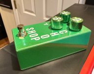
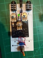
Fun project that you can knock out in a few hours. I did not adjust the internal trimmers, I just let it rip. It worked straight away on the PedalPCB auditorium platform and then I boxed it. It has plenty of gain and the sound is both useable and adjustable. It can sound like fuzz or overdrive. I dig it!
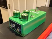
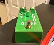
The components are mostly easy to find and the board layout is great. I used a Taiway short bat on/off/on switch and a light touch footswitch. I used a powder coated 125b enclosure and fitted it with Lumberg jacks, a PedalPCB top jack plate, a green 5mm LED
Have a great weekend everyone!

 and 20mm anodized green knobs with vinyl labels.