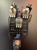
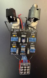
Raincoat No signal LED works

Plaidesaurus

Active member
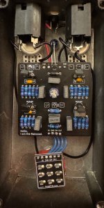
Built 2 Raincoats and having the same issue with both, which leads me to think I must have put some components in the wrong place. I've built several of these before to give to other players so not sure what's up. I've tried different sets of transistors on both. They all checked out as working on my meter. Even tried some 2n3904s but no luck. Clean signal works fine, LED lights up when engaged, but no sound from either when engaged. Have looked over multiple times but...
FYI, the unboxed board did have transistors in place and was mounted in a box when I demoed. I'm hoping someone sees something here I've overlooked. THX
 

Attachments

  • IMG_3025.jpeg
    IMG_3025.jpeg
    486.5 KB · Views: 25
  • IMG_3024.jpeg
    IMG_3024.jpeg
    550.3 KB · Views: 25
  • IMG_3023.jpeg
    IMG_3023.jpeg
    478.1 KB · Views: 25
What swelchy was saying is you would need rotate the 3904s 180 degrees.
Also, make sure you aren't plugging into the out jack. Easy to do when the pedal is inverted.
Yeah, I actually tried that with the pinout on the 3904s correctly placed just a bit ago. No luck. Can't help but think I've put in some wrong value components. Going to remove a couple of those 470Ps and make sure they read correctly.
I use a test box to drop the finished boards into to test so the enclosure is always as it would be on a pedalboard. Still, I have made that mistake in the past. Thx
 
The only thing that stands out in your build are the sockets for the transistors. You don't really want to use sockets for these as they can cause a poor connection. Sockets are great for IC's which have many leads, but a transistor only has 3 and none of them are able to impart mechanical locking force when inserted into the socket. It's possible your issue is related to these.

You can fix it either by desoldering and removing the sockets and installing the transistors directly, or, verify the female pin hole of each socket has continuity with its PCB solder pad, and then install the transistors and solder them in place.

Another thing that can cause the issue you're having is if the signal is grounded. Use the continuity function on your meter to see if the IN and GND solder pads at the footswitch have continuity.
 
Clean signal works fine, LED lights up when engaged, but no sound from either when engaged.

This is what happens when you plug the cables into the wrong jacks. I'm not saying that's your issue, but make sure it's not. It's easy to forget when the knobs are facing down that the jacks are oriented the opposite of what we're used to.

I don't have an audio probe but will go ahead and get one. I'm sure it's straight forward but if anyone has seen a good video on how to, please send along.

Typically, you make them yourself.

 
This is what happens when you plug the cables into the wrong jacks. I'm not saying that's your issue, but make sure it's not. It's easy to forget when the knobs are facing down that the jacks are oriented the opposite of what we're used to.


Typically, you make them yourself.

Fantastic, I'm on it. TY!
Make sure your 470pF MLCCs are actually 470pF and not 470nF.
I pulled one of the 470s and they are definitely pf caps. Going through all the suggestions on this thread. Continuity works on everything that was suggested. Looked back over my build list and I've built about a dozen Raincoats. I build one and then another musician friend chimes in to get one. It's an awesome and flexible pedal. The audio probe is my next more. Thx
 
The only thing that stands out in your build are the sockets for the transistors. You don't really want to use sockets for these as they can cause a poor connection. Sockets are great for IC's which have many leads, but a transistor only has 3 and none of them are able to impart mechanical locking force when inserted into the socket. It's possible your issue is related to these.

You can fix it either by desoldering and removing the sockets and installing the transistors directly, or, verify the female pin hole of each socket has continuity with its PCB solder pad, and then install the transistors and solder them in place.

Another thing that can cause the issue you're having is if the signal is grounded. Use the continuity function on your meter to see if the IN and GND solder pads at the footswitch have continuity.
I did check for continuity on all points you suggested. Everything is solid. I usually use those transistor sockets due to all the suggestions on this forum. Still new to building and like having the ability to try different transistors. THX
 
Back
Top