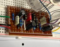
First vero build - circuit works but output is barely audible.

zakco

Member
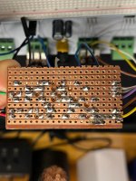
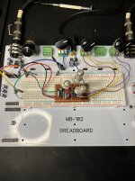
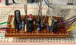
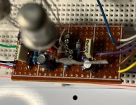
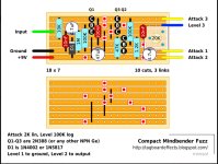
My first Vero build. It’s the Mind Bender as per this layout:
The only modification is the trimpot is wired off-board to a regular pot

Voltages at all transistors are good, all controls function as expected but the output is barely audible - probably 30db quieter than it should be, but I can clearly hear that other than the output level, the volume, attack and bias pots are working. The gigantic GT404s make it difficult to see the top layout, but I've taken photos from a few angles, so hopefully everything is visible.

Any help would be appreciated, thanks!
 

Attachments
  • imgMINDBENDER VERO.JPG
    imgMINDBENDER VERO.JPG
    261.1 KB · Views: 36
  • IMG_3255.jpg
    IMG_3255.jpg
    490.1 KB · Views: 41
  • IMG_3256.JPG
    IMG_3256.JPG
    500.6 KB · Views: 36
  • IMG_3252.jpg
    IMG_3252.jpg
    322.3 KB · Views: 28
  • IMG_3253.jpg
    IMG_3253.jpg
    334 KB · Views: 27
  • IMG_3254.jpg
    IMG_3254.jpg
    340.3 KB · Views: 29
Last edited:
You can poke around the signal path with a point to a small amp. (Audio probe). That way you'll know where the issue is in the chain. Or you can use the multimeter's continuity beepers and go through each connection. It's less time than hastily building another.
 
I saw this comment and assumed that it had been fixed. Also, I tried reversing the cap tonight and got no output at all.
Well maybe, it seems like the wrong orientation to me but wouldnt be the first time I was wrong. Be careful with vero just because things are verified even they aren’t always right. Dirtbox layouts eqd seamachine one of the pots is wrong and does nothing its verified. I know I commented what the fix was and that it wasn’t right. I havent looked in a few years but I know months later it still wasn’t fixed.
 
Well maybe, it seems like the wrong orientation to me but wouldnt be the first time I was wrong. Be careful with vero just because things are verified even they aren’t always right. Dirtbox layouts eqd seamachine one of the pots is wrong and does nothing its verified. I know I commented what the fix was and that it wasn’t right. I havent looked in a few years but I know months later it still wasn’t fixed.
Noted. I'm definitely questioning the layout after getting the same result twice.
 
I've never understood that...

I've seen threads on other forums where the person uploading the layout acknowledges there's a mistake and then doesn't post the fix.
*So, you want everyone to DL the broken layout and then read a 30+ page thread to find the fix in text-form that's buried within the thread , or even in a separate thread.*

Threads like that on FSB, DIYSB... KitRae's Muff pages need a few tweaks, too.


I understand that on some websites, the ability to amend a post can time out (talkbass, for example) — that's one of the reasons I like it here*, I can go back and fix something, replace a graphic and at the least make a note that the post has been edited.


Vive le PPCB forum, vive le PPCB forum LIBRE! 🤘


Also, most vero layouts that are verified may just mean the circuit works — it is NOT an indication that the circuit laid out is an accurate representation of the original circuit it's meant to be a clone of.


[*PS: ] Just noticed some much older posts that are no longer editable — so it seems there's a time-limit here on this forum too now (wonder what it is exactly). If absolutely necessary, you can always ask Robert to change something, but be aware he's a busy man — how important is the change?...[/PS]
 
Last edited:
well ive eyeballed the heck out of this layout a few times now and cannot find anything wrong with it vs. the schematic.

yes, collector voltages. Here's a complete measurement:

Q1c: 7.29
Q1b: 0.06
Q1e: 0
Q2c: 0.14
Q2b: 0.07
Q2e: 0
Q3c: 7.5
Q3b: 0.15
Q3e: 0
Q3e should not be zero.
it should have some voltage. like 0.1v or thereabouts.

there's a clue.
1783902368310.png

?perhaps there's a short somewhere causing Q3e to have continuity to ground (not seeing anything in the layout that would cause this either..)
 
I think the image of the back might be mirrored, look at the wire colors and the direction they're leaving the board.
I was finding it extremely difficult to navigate the layout in reverse when the board was flipped, so I mirrored the image to make the cuts match the front view, to help me confirm that they are in the right place (or so I thought.) Which leads me to a real rookie question...If I was wrong about that, why are the red dots in the same location on the front diagram and the back? Don't the cut locations coincide directly with their relationship to the components, regardless of the whether the image is mirrored or not?
 
Try crimping a 100k-470k between the collector and base of Q1. It may not have enough leakage which is why the bias is funky.
yep this was my initial thought but the guy is claiming:
breadboarded first and it sounded fantastic. The volume drop happened when I transferred the circuit to Vero.

so assuming all components are the same, there has to be a build error somewhere.

yes, collector voltages. Here's a complete measurement:

Q1c: 7.29
Q1b: 0.06
Q1e: 0
Q2c: 0.14
Q2b: 0.07
Q2e: 0
Q3c: 7.5
Q3b: 0.15
Q3e: 0
and ill say it again. Q3e should not be zero.
 
Back
Top