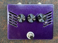
Help : Black Eye

Guipouette

New member
Hello to everyonne !

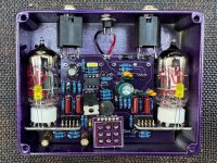
I just finished to build my first one, but the pedal don's works :unsure::cry: !

Do you have an idea what could be the issue(s) ?

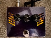
When the pedal is off, the bypass is ok. The sound from the guitar to the amp work. But when the pedal is on, no sound (or just a few noise) and the DEL is on.

Already thanks for the help !

Florian
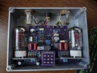
 

Attachments

  • 20260725_203737.jpg
    20260725_203737.jpg
    559.9 KB · Views: 32
Are you getting indicator lights?
I recommend starting with checking the B+ power to the tubes. What is the recommended power supply for that pedal? I assume it would need to be capable of high current switching supply to go from low voltage to 250VDC while also supplying the tube filaments (300ma at 12VDC for two 12AX7 type tubes).
 
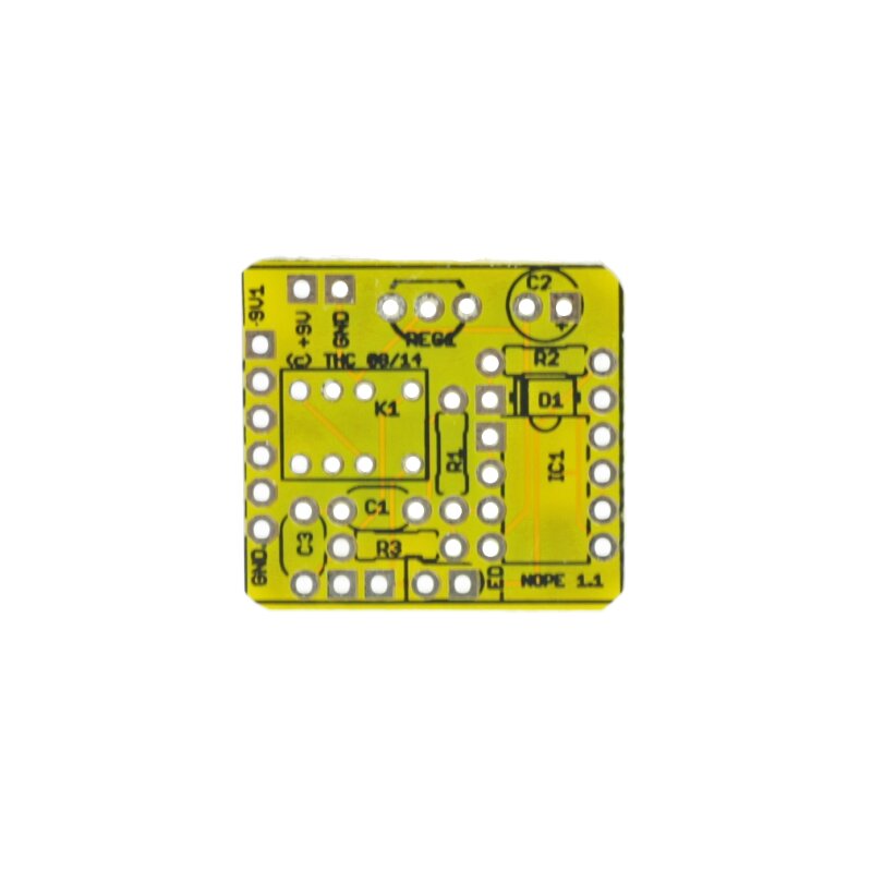
Your footswitch board is upside down. The writing should be on the top so you can read c2c. Not saying it’s the only problem but it is a problem. You will likely need to order a new board as getting a footswitch off without damaging it can be a challenge.
 
Last edited:
Your footswitch board is upside down. The writing should be on the top so you can read c2c. Not saying it’s the only problem but it is a problem. You will likely need to order a new board as getting a footswitch off without damaging it can be a challenge.
it looks like it's upside down but i dont think it is.

Check this other build reports :


The usual suspects on this build are the tube-daughterboards connectors, with small soldering pads very close to each other.
 
Last edited:
Are you getting indicator lights?
I recommend starting with checking the B+ power to the tubes. What is the recommended power supply for that pedal? I assume it would need to be capable of high current switching supply to go from low voltage to 250VDC while also supplying the tube filaments (300ma at 12VDC for two 12AX7 type tubes).
we need 9V+ with at least 500mA to make it work.
There's a voltage pump implemented in the circuit, to make it feed the tubes around 200V from a standard 9V DC power supply.

Good point, that could easily be the issue.
 
Last edited:
Thank's for the answer ! I have to find a better power. Today I have only 9v -1A but the voltage isn't very good.
My second alim has a real 9v (but 300ma), but the DEL is already better
When I got one , I tell you

It could be the solution 🤞
 
Power is important with these pedals. I recommend a 1 spot. I would still check the footswitch board. I have never built a c2c board that didn’t have it labeled on top. (Just my experience). It usually says c2c and has a board label like TB or BO. Maybe there are some that don’t. He also usually runs the traces for the footswitch on the bottom. It’s worth taking it out of the box for a quick visual inspection.
 
Last edited:
I would still check the footswitch board.

If there's a doubt on the 3PDT connections, it's possible to figure it out and hand-wire some new 3PDT.

It's going to be jack IN, PCB IN, GND, V+, PCB OUT, jack OUT, not necessarily in that order.

With a multimeter on continuity test we can see which one is GND, and figure out the rest with a few attempts.

The best would be to add an extra relay bypass, to make the switching process almost completely silent.
There is enough space to squeeze it in the enclosure, that's what i did on my build.
I just had to put the relay bypass pcb inside some small plastic bag to isolate it from the main pcb.
 
I found what the 3PDT pads are, from my own debugging thread :


There's also the post where the circuit designer told me about the power requirements:

 
Last edited:
Yeah the other thing that stands out to me on that is the footswitch has a white outline where it would go. That’s usually on the side the switch/part is mounted on. It may work upside down but I don’t think it will work properly.
 
it's working
dont forget the Extra Bass Mode toggleswitch !

 
let's ask @jcpst , looks like he had the same 3PDT breakboard.
I suspect there are some other markings on the other side.
Oh wow, I never noticed that I installed it upside down, even though there is a footswitch-sized white component outline printed on it!

The fact that I did this on two c2ce builds tells me it works both ways. I did a visual inspection of the traces and as far as I can tell it will work both ways. Pretty clever design.
 
Back
Top