Tuner (PCB320) — Footswitch tap-to-toggle or hold and Build Photos, anyone?

OGCGFX

New member
I'm building the PedalPCB Tuner (PCB320, not Q-Tune). Two things the build doc doesn't cover:

1. Footswitch behavior — is it tap-to-toggle (press once to engage, again to bypass) or momentary/hold (hold to tune, release to bypass)? Is this configurable in firmware?

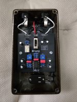
2. Standoff/spacer placement — the doc lists M3 female/male standoffs and screws by type and quantity but doesn't show which mounting points each goes to (board-to-board vs board-to-enclosure, etc). Would anyone be willing to post a couple of photos of the assembled hardware stack so I'm not guessing? Would save a lot of reverse-engineering time.

Thanks!
 
I apologize, I didn't see this thread until now.

1. Footswitch behavior

Standard tap-to-toggle latching behavior.

I've never considered momentary switching in a tuner but it actually makes sense... although personally I think I'd just leave the tuner on all the time.

2. Standoff/spacer placement

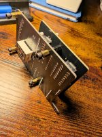
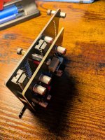
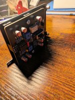
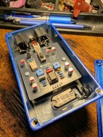
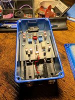
I'll see if I can post a picture of the assembled stack outside of the enclosure.


One other thing that you didn't ask but needs to be added to the build doc: start with both trimmers at noon. You most likely won't need to adjust them, mine seems to work just as well regardless of where they are set, but they are available just in case.
 
Not boxed yet but you get the idea. The black screws in the first photo represent what will go thru the faceplate and the enclosure.
 

Attachments

  • PXL_20260916_212951691.jpg
    PXL_20260916_212951691.jpg
    277.2 KB · Views: 20
  • PXL_20260916_212957680.jpg
    PXL_20260916_212957680.jpg
    221.4 KB · Views: 20
  • PXL_20260916_213002972.jpg
    PXL_20260916_213002972.jpg
    241.3 KB · Views: 20
  • Like
Reactions: Nic
One other thing that you didn't ask but needs to be added to the build doc: start with both trimmers at noon. You most likely won't need to adjust them, mine seems to work just as well regardless of where they are set, but they are available just in case.
Are those buffer related or else ?
 
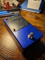
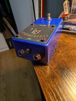
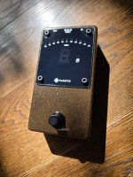
Here's what the finished pedal looks like. Kinda silly to build your own tuner from a financial standpoint. But kinda silly to be building your own pedals too so...

This thing is very cool. Stupid stable and very bright. I left the trimmers at 50%. I have no idea what they do. I thought I had another jack/power faceplate kicking around but I guess not. It'll go in with my next order. Its a Tayda blue metallic 125b. I overdrilled the LEDs just slightly so they'd line up with the faceplate and I'd look like I knew what I was doing. On the other hand I totally nailed the cutout for the display with a drill bit and some nippers but nobody will see it. I thought about getting creative and doing a cutout for the USB port but decided to quit while I was ahead.

Is this something you need? Likely not. Is it something you should build? Fuck yeah... You rarely get the chance to do a multiboard build with a crapload of holes on the front that requires a bunch of weird standoffs and ends up looking and working this trick. Don't even need my name on this one.
 

Attachments

  • PXL_20260920_003532768.jpg
    PXL_20260920_003532768.jpg
    243.6 KB · Views: 18
  • PXL_20260920_003557488.jpg
    PXL_20260920_003557488.jpg
    190.2 KB · Views: 17
  • PXL_20260920_003833962.jpg
    PXL_20260920_003833962.jpg
    282.8 KB · Views: 17
  • PXL_20260920_003846836.jpg
    PXL_20260920_003846836.jpg
    267.2 KB · Views: 16
Awesome! Thanks very much. I did the reverse engineering head scratching for about 30-40 mins and figured out the standoffs.

Another question on dealing with all those LEDs, which seem to be the bane of my noob existence in pedal building. Do you guys use standoffs/spacers/tubes for those or some other method to get them all the right height?
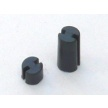
ie these at 6mm high 3mm width?
1790119262022.png
 
Awesome! Thanks very much. I did the reverse engineering head scratching for about 30-40 mins and figured out the standoffs.

Another question on dealing with all those LEDs, which seem to be the bane of my noob existence in pedal building. Do you guys use standoffs/spacers/tubes for those or some other method to get them all the right height?
ie these at 6mm high 3mm width?
View attachment 124946
Nope, take a look at mine. I provided many pictures to help other builders.
I inserted every led on the board, then secured the board in the enclosure (tayda pre drilled) using screws/standoffs
Then I just let the led find it's hole and solder it in place.
If you ordered the drilled enclosure from tayda, they will all stop at the base ridge of the led. I used clear flat top ones and with the official faceplate they were coming just flush. With standard 3mm, it should like the image Robert put for the pcb.

 
Last edited:
Yep, that's how I do it.

If I need them to be perfectly flush (flat top LEDs, for example) then I will use masking tape to attach something flat (drivers license, another PCB, etc) across the face of the enclosure for the LEDs to rest against while soldering.

@Nic I think you still have the protective film on that faceplate.
 
@Nic I think you still have the protective film on that faceplate.
Should not, I removed one from the back (but left the 3m backing in case I changed my mind) and one from the top 2 minutes before taking pictures... and it already attracted some dust. I haven't wiped it to remove any residual adhesive.
 
Back
Top