Finishing Kilimanjaro - Measuring / Biasing

joelorigo

Well-known member
I have a Kilimanjaro that I am trying transistors on. I have a "3 knob Tone Bender PNP" setup from Small Bear that I am trying. These:

Obviously I am not sure these transistors will work but I am confused about what steps to take to find out. I have the transistors inserted and now what exactly?
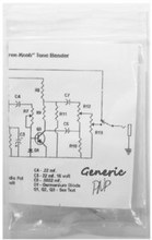
 

Attachments

  • IMG_5748.jpg
    IMG_5748.jpg
    650.1 KB · Views: 21
I think so. I asked for confirmation on that first in this post:

The way I have them inserted is each lead in the triangle shape matching the triangle shape of the pads. No crossing leads. If that makes sense.
 
I think so. I asked for confirmation on that first in this post:

The way I have them inserted is each lead in the triangle shape matching the triangle shape of the pads. No crossing leads. If that makes sense.
There's a little tab on the transistors that should line up with the tab on the PCB silkscreen, there are a few manufactures who put that tab on a different leg I think, so might not hurt to look at data sheets
 
I have the tabs of the transistors lined up with the tabs on the PCB. The transistors don't have any identifiable markings so that is why I asked in that thread about the pinout.
 
I believe you can determine with a DMM set to DIODE mode. There is a center pin, that is where you attach the BLACK lead. Touch each of the others with the RED lead and record the readings. The higher reading is the base-emitter junction. As others said, the emitter is typically the tabbed pin.
 
The Kili is an offshoot of a Tone Bender MK1/Zonk Machine. This circuit is finicky with transistors.
Here are my observations on TB MK1 transistors:

 
  • Like
Reactions: fig
I believe you can determine with a DMM set to DIODE mode. There is a center pin, that is where you attach the BLACK lead. Touch each of the others with the RED lead and record the readings. The higher reading is the base-emitter junction. As others said, the emitter is typically the tabbed pin.
All the transistors have larger readings on the base pin and tab pin versus the base and non-tab pin.

Q1 .210 vs .206
Q2 .182 vs .179
Q3 .177 vs .170

So it seems like they were inserted correctly
 
Last edited:
  • Like
Reactions: fig
The Kili is an offshoot of a Tone Bender MK1/Zonk Machine. This circuit is finicky with transistors.
Here are my observations on TB MK1 transistors:

I also have done a bunch of research on the mkI. I first tried some transistors I already had based on that research.
These are what I got from Small Bear.
Q1 63 leakage 35
Q2 79 leakage 84
Q3 108 leakage 100

Some of the numbers match with what worked for you, but not all of them.
 
Yeah, what you bought from Small Bear is a set for a TB Mk3 or 3 knob TB which is a different beast. Out of that set you bought from SB, try switching Q2 & Q3 around. For Q1 use something with gain of 60-80 and leakage of 200-350ua, maybe more. You could use the Q1 from that SB set but you will have to add a resistor from Q1 collector to Q1 base, like a 1meg or so.
 
Yeah, what you bought from Small Bear is a set for a TB Mk3 or 3 knob TB which is a different beast. Out of that set you bought from SB, try switching Q2 & Q3 around. For Q1 use something with gain of 60-80 and leakage of 200-350ua, maybe more. You could use the Q1 from that SB set but you will have to add a resistor from Q1 collector to Q1 base, like a 1meg or so.

Ah I see. The reason I bought them for this is because Small Bear told me that their 3 TB work "well in a MK I type build."
I will try swapping Q2 & Q3. For that Q1 suggestion, I have 1M resistors, what does the resistor do? Do I wrap the resistor leads around the transistor leads and solder? Can I try without soldering first to see if it works?
I think you'd get an idea if it works without soldering first
 
The 1M resistor is just a starting place. Your Q1 has very little leakage and Q1 in a TB Mk1 needs leakage in order to pass signal and work. Same with the Kilimanjaro circuit. The 1M resistor simulates transistor leakage for Q1.
This is where breadboarding the circuit would come in handy... Build up the circuit on breadboard and that way you can test it out and modify it to your liking before committing it to the soldered PCB.
 
Back
Top