martanthony
New member
Hi all!
New forum member here, hoping for some insight with an issue I'm having on my second build!
Using an audio probe, I've found that there's a significant drop in signal volume and tone immediately after C1 – which, when you look at the schematic and find that it's the first component on the board, is quite embarrassing. I've measured the cap and it reads 100.3nF, so generally in spec. The signal after the following J201 is also very weak. I can't see anything on or around the board that would suggest why there's such a change in the signal quality. I don't have a particularly strong background in electronics, but my understanding of capacitors is that their primary use isn't for tone shaping.
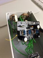
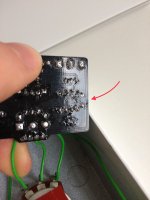
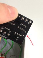
My question is: can a capacitor still read correctly but not be functioning correctly? Advice or suggestions would be very welcome! Build shots below for reference. Apologies in advance for the melty-looking PCB and monochrome wiring choice, lots of learning still to do


Mart
New forum member here, hoping for some insight with an issue I'm having on my second build!
Last year I picked up a Carmine Overdrive board and set about building what I'd hoped would be a replacement for my unreasonably noisy EQD Crimson Drive V2. It passed very little signal once assembled; the Cross Contaminator build I had on the go was also giving me issues, so my enthusiasm for problem-solving waned until I recently had the urge to get the pedals working.
After discovering that I'd wired the OC139 in the wrong way and fixing that issue, the pedal is still passing a weak signal: with the drive and level maxed, the tone is very bright, edgy, with not a lot of headroom. Rolling back the drive slightly results in a massive drop in signal. I built an audio probe from these instructions and feel I might have discovered where the issue lies.
After discovering that I'd wired the OC139 in the wrong way and fixing that issue, the pedal is still passing a weak signal: with the drive and level maxed, the tone is very bright, edgy, with not a lot of headroom. Rolling back the drive slightly results in a massive drop in signal. I built an audio probe from these instructions and feel I might have discovered where the issue lies.
Using an audio probe, I've found that there's a significant drop in signal volume and tone immediately after C1 – which, when you look at the schematic and find that it's the first component on the board, is quite embarrassing. I've measured the cap and it reads 100.3nF, so generally in spec. The signal after the following J201 is also very weak. I can't see anything on or around the board that would suggest why there's such a change in the signal quality. I don't have a particularly strong background in electronics, but my understanding of capacitors is that their primary use isn't for tone shaping.
My question is: can a capacitor still read correctly but not be functioning correctly? Advice or suggestions would be very welcome! Build shots below for reference. Apologies in advance for the melty-looking PCB and monochrome wiring choice, lots of learning still to do


Mart

