Black Tiger Boost build issues now possibly made worse

FleeRemi

New member
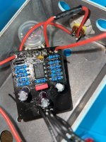
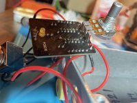
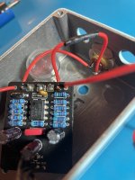
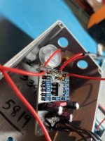
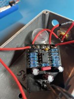
So i'm working on my first ever build, a pedalpcb Black Tiger boost. I finished last night and it worked decently well but had a weird "farty" sound to the signal like something on the board might not be functioning correctly. I decided to reflow all of the connections on the components of the pcb, and now when I engage the switch, the pedal has little-to-no signal. Signal is perfectly fine in bypass, and if i turn the knob down all the way, the dry signal will come thru in a bypass-like-manner.

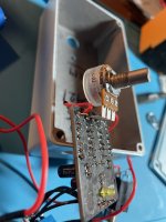
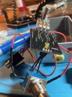
What did i screw up? Worried i may have fried a capacitor or possibly the 4558 chip. Including a bunch of pictures that may or may not be of help.

Thank you in advance for any help!!
 

Attachments

  • IMG_8775.jpg
    IMG_8775.jpg
    483.6 KB · Views: 31
  • IMG_8782.jpg
    IMG_8782.jpg
    361.1 KB · Views: 32
  • IMG_8781.jpg
    IMG_8781.jpg
    374.1 KB · Views: 24
  • IMG_8780.jpg
    IMG_8780.jpg
    392.8 KB · Views: 25
  • IMG_8778.jpg
    IMG_8778.jpg
    359.9 KB · Views: 24
  • IMG_8777.jpg
    IMG_8777.jpg
    384.8 KB · Views: 29
  • IMG_8776.jpg
    IMG_8776.jpg
    426.4 KB · Views: 32
Yeah, that kind of heat doesn't seem excessive, and if you weren't sitting on those pins for too long that shouldn't have done it. On components like that I usually do one leg, let it cool, then move on to the next, but then again I usually socket ICs like that so as not to fry them and so I can swap them out easily if I suspect a problem there. Do you have a DMM? Can you check the voltages on each of the IC pins?
 
Yeah, that kind of heat doesn't seem excessive, and if you weren't sitting on those pins for too long that shouldn't have done it. On components like that I usually do one leg, let it cool, then move on to the next, but then again I usually socket ICs like that so as not to fry them and so I can swap them out easily if I suspect a problem there. Do you have a DMM? Can you check the voltages on each of the IC pins?
I have a DMM, though still a bit unsure how to use it properly. How would I go about using the DMM to check that? (or if you could point me in the direction of a guide, either way I really appreciate it!)
Sorry, i'm still very new to this, watched a ton of videos on proper soldering techniques but still iffy on some of the fundamental electronics knowledge.
 
Connect the negative (black) lead to ground, set the meter to read voltage, and then with the pedal powered up start with pin 1 (the one next to the dot) and read the voltage. Then go down that side reading the voltage on each pin. If the voltage is fluctuating, capture the lowest voltage and the highest voltage. Then jump across to pin 5 (the one on the bottom right -- diagonal from pin 1), and then do the same thing reading them from the bottom to the top.
 
Connect the negative (black) lead to ground, set the meter to read voltage, and then with the pedal powered up start with pin 1 (the one next to the dot) and read the voltage. Then go down that side reading the voltage on each pin. If the voltage is fluctuating, capture the lowest voltage and the highest voltage. Then jump across to pin 5 (the one on the bottom right -- diagonal from pin 1), and then do the same thing reading them from the bottom to the top.
Sorry for getting back to you so late, thank you for this. I just did the test, and going in the order you mentioned:

Pin 1 - 2.5-2.6
Pin 2 - 3.6-3.7
Pin 3 - 0
Pin 4 - 0
Pin 5 - 0.1-0.2
Pin 6 - 8.0-8.2
Pin 7 - 8.2-8.3
Pin 8 - 16.9

Feel like any 0s is bad right?
 
Sorry for getting back to you so late, thank you for this. I just did the test, and going in the order you mentioned:

Pin 1 - 2.5-2.6
Pin 2 - 3.6-3.7
Pin 3 - 0
Pin 4 - 0
Pin 5 - 0.1-0.2
Pin 6 - 8.0-8.2
Pin 7 - 8.2-8.3
Pin 8 - 16.9

Feel like any 0s is bad right?
just to clarify/make sure I did it right, for ground i used the connection on the footswitch lug from the ground on the PCB, and i had my multimeter dial set to the 9v setting, assuming that was the right one.
 
Sorry for getting back to you so late, thank you for this. I just did the test, and going in the order you mentioned:

Pin 1 - 2.5-2.6
Pin 2 - 3.6-3.7
Pin 3 - 0
Pin 4 - 0
Pin 5 - 0.1-0.2
Pin 6 - 8.0-8.2
Pin 7 - 8.2-8.3
Pin 8 - 16.9

Feel like any 0s is bad right?
no, pin 4 is ground, you would expect that to be 0, and pin 3 is the input, which if there isn't a signal going into the pedal, could read 0, but I'm not 100% sure of that. I have to go back through my builds and see if I have one with a 4558 to check to see if those voltages are in the ball park. I'm guessing that if you're seeing 16.9V on pin 8, you are powering this thing with 18V?
 
no, pin 4 is ground, you would expect that to be 0, and pin 3 is the input, which if there isn't a signal going into the pedal, could read 0, but I'm not 100% sure of that. I have to go back through my builds and see if I have one with a 4558 to check to see if those voltages are in the ball park. I'm guessing that if you're seeing 16.9V on pin 8, you are powering this thing with 18V?
it's a 1Spot, says 9v. Maybe it does either/or? I'm not entirely sure
 
I think the 1 spot is capable of 18V -- it may have a switch or something to go between 9 & 18V. I don't have a 1 spot, so I'm not sure.

If you're seeing 16.9V on pin 8, I'd be expecting about 8.4V on pin 5. You may want to check R102. There should be continuity between one leg of R102 and pin 8, and the other leg of R102 should have continuity to pin 5.

Maybe somebody who knows a little more than I do can chime in here.
Damn, i appreciate the help still! I reflowed on R102, sucked away some of the extra solder that got thru the other side, reflowed pin 5, and still getting the same 0.1 reading.
 
Last edited:
Did you check your power supply to see how many volts you are sending to the pedal -- 16.9V on pin 8 is out of spec per the data sheet. It can handle up to 18V max, but it's recommended VCC supply should be between +/- 5V to +/-15V.
 
Did you check for continuity? Does your DMM have an audible continuity tester?
I didn’t but i will when I get home from work later, I believe mine has a buzzer for that function.

Did you check your power supply to see how many volts you are sending to the pedal -- 16.9V on pin 8 is out of spec per the data sheet. It can handle up to 18V max, but it's recommended VCC supply should be between +/- 5V to +/-15V.
I gave it a quick look and didn't see a switch or anything, just says 9v on the side of it. Is there a way to easily test with the multimeter what its sending?
 
Link to Black Tiger Boost schems :


I didn't check the whole thread, but i see there are some doubts about the power supply readings.

Is this the one ?

Screenshot 2024-02-04 at 07-36-25 Truetone 1 Spot 9V_DC.png

In this case, there is no way it reads 23V, and you won't find any switch, this power supply can only provide 9V DC.
I have 2 or 3 of those, and they always read 9.45V or so.

23.5 what ? is there a V symbol for Volts?

You need to set your meter on DC voltage reading (Direct Current and not Alternative current), black probe on ground (any ground point in the circuit), red probe on pcb 9V+.

DC current symbol on your meter :

200px-Direct_current_symbol.svg.png

I also understood there are some doubts about a fried 4558 ? They are quite sturdy, and usually don't get overheated easily.

Chris is right (about this topic), i totally agree with reply #5.

If you have an other gain effect, you could try it with this chip, see if it works or not. 4558 are compatible replacement for most dual op-amps, like TL072, etc. which are often found in various guitar effects.
They are quite cheap and very common, so you can also get a new one to avoid any doubts about it.

Edit : i just noticed that the 4558 isn't socketed. It could be tricky to unsolder it. I would check carefully the rest of the circuit before removing this chip.

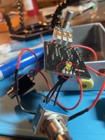
I'd suggest to shorten these legs, to avoid any short with the enclosure. Looks like they are just as high as the status led :
IMG_8780.jpg
If i may, i'd say that your soldering technique is quite interesting, i can see some beautiful shapes, but these soldering pads are somewhat irregular. Looks like a few pads, located toward the middle of the pcb, are maybe a little bit light on the solder ?

You could also clean the tiny spaces between pads with your Soldering Iron (moving quickly), to avoid shorts.

On a side note, it looks like the Led is stuck to the board. It might be hard to make it fit in your Plastic Led Mounting Clip ?
 
Last edited:
Back
Top