Tone bender mk1.5

Johnnyorange500

Active member
Hi,

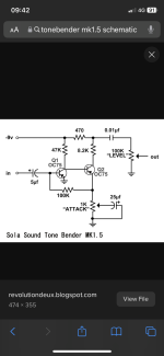
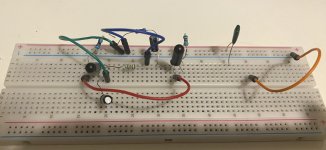
I’m having trouble with my MK1.5. I had it all wired up and ready to go, but I couldn’t get it to work. So my friend said he’d have a go and also couldn’t get it to work; he de-solder the parts and had a go at breadboarding it and still no luck. So I picked it up from him. This was the layout he did for the breadboarding. Anyone see what’s wrong with it?

Cheers
Johnny
 

Attachments

  • IMG_5564.jpeg
    IMG_5564.jpeg
    269.3 KB · Views: 26
Last edited:
Maybe a redundant question, but just checking that you understand that this is an atypical positive ground circuit? It won't play nicely with other more common negative ground ones. For purposes of argument, maybe try just a 9V battery to isolate it from the rest if using a common PSU. In such cases, everything polarised is reversed from the normal (elcaps with positive legs to ground, LEDs, power, and so on).
 
What’s going on at J28?

Maybe a redundant question, but just checking that you understand that this is an atypical positive ground circuit? It won't play nicely with other more common negative ground ones. For purposes of argument, maybe try just a 9V battery to isolate it from the rest if using a common PSU. In such cases, everything polarised is reversed from the normal (elcaps with positive legs to ground, LEDs, power, and so on).
Yeah, I know. I had it all wired and it wasn’t working. So gave it to a friend who couldn’t get it working too. So he stripped it all and stared again and said it wouldn’t work he then tried to breadboard it it’s pretty primitive I know. And no where near right. I haven’t breadboarding myself so I’m gonna scrap this and start again the way I stated and troubleshoot it that way. Sorry to waste people time. With this. Thanks for the help and suggestions tho. Much appreciated. Maybe my mates was having a bad day.
 
As it happens, I have a couple of OC75s lying around. Might be fun to breadboard it and see if I can get it to work myself. I find these positive ground circuits pretty problematic, counter-intuitive, what have you, myself, but it sounds like a worthy challenge. Give me a day or two.
 
As it happens, I have a couple of OC75s lying around. Might be fun to breadboard it and see if I can get it to work myself. I find these positive ground circuits pretty problematic, counter-intuitive, what have you, myself, but it sounds like a worthy challenge. Give me a day or two.
Nice one! Well it’s been a challenge for both myself and my friend. All the parts were testing ok. So yeah, problematic for sure. I made a Tonebender mk1 and for some reason found that easier. I’m not a fan of vero board tho so.. found it tricky. Enjoy the old vintage board more. Good luck mate. 👍🏻
 
Nice one! Well it’s been a challenge for both myself and my friend. All the parts were testing ok. So yeah, problematic for sure. I made a Tonebender mk1 and for some reason found that easier. I’m not a fan of vero board tho so.. found it tricky. Enjoy the old vintage board more. Good luck mate. 👍🏻
tb_mk1.5_breadboard.jpg
I can confirm, with all due apologies for the hideous messy layout, that the circuit works. But you will certainly need all the parts that @Big Monk mentioned for it to do so.

You'll notice that the battery wires are reversed. Build it as if all connections are 'normal' and reverse the battery connections at the end.

Note the added bells and whistles: reverse polarity protection diode and LED to confirm you're getting current to the board.

Without bias trimmers for the 47k and 8k2 fixed resistors, it's a bit hit and miss to get sustain without gating. If I were committing to this, I'd put in some trimmers to get all the joy of properly biased Germaniums. Good luck. Hope you get yours to work sooner than later.
 
View attachment 66259
I can confirm, with all due apologies for the hideous messy layout, that the circuit works. But you will certainly need all the parts that @Big Monk mentioned for it to do so.

You'll notice that the battery wires are reversed. Build it as if all connections are 'normal' and reverse the battery connections at the end.

Note the added bells and whistles: reverse polarity protection diode and LED to confirm you're getting current to the board.

Without bias trimmers for the 47k and 8k2 fixed resistors, it's a bit hit and miss to get sustain without gating. If I were committing to this, I'd put in some trimmers to get all the joy of properly biased Germaniums. Good luck. Hope you get yours to work sooner than later.
Nice one! You’re a star. Thanks for the pic too as I’m more of a visual learner so will help. Thanks again. I feel like I can have a good go at it myself now. 👍🏻
 
Nice one! You’re a star. Thanks for the pic too as I’m more of a visual learner so will help. Thanks again. I feel like I can have a good go at it myself now. 👍🏻
Pleasure. I cut my teeth on these and they can be quite difficult to get to work. Shout if you get stuck. Sorry, forgot to mention that Q2 is reversed (EBC) to try to make it more user-friendly.
 
Back
Top