SOLVED Sproing Deluxe tremolo stops at high speed.

Giorfida

Well-known member
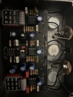
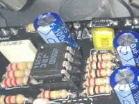
Just completed the Sproing deluxe using the BOM as listed here. The only thing I did out of the ordinary is using a green led for the 5mm indicator (but did use the 3mm red for the vactrol)
At lower speeds it works fine, then slightly above halfway when the speed gets to 9 on the dial (fender amp knobs, where 10 is the highest) it stops oscillating- the ldr led comes on full, and the indicator above the footswitch goes off.

any suggestions where to start looking?
 
Last edited:
I’d like to attach videos to show how the ldr/led speeds up then goes solid at around 9. Also have one showing how the switch indicator goes out when the ldr goes solid (slightly before, actually). I would think it’s parasitic oscillations.
Will dig in deeper and probe/check voltages later. Just wanted to see if anyone else experienced it and what they did to remedy
 

Attachments

  • IMG_5461.jpeg
    IMG_5461.jpeg
    333.5 KB · Views: 20
Just tried mine - tremolo works across the whole speed range.

I was hoping to spot check some of your component values, but that pic is pretty dark/ blurry.

What did you use for an LDR?
 
Just tried mine - tremolo works across the whole speed range.

I was hoping to spot check some of your component values, but that pic is pretty dark/ blurry.

What did you use for an LDR?
I’ll get a better pick later. Already checked values but a second wet of eyes never hurt.
I used the 5516 I believe that Tayda has. I know that’s normally the problem spot, but here it’s the led driving it goes solid.
Im also going to try a different IC for the oscillator in case I just have a noisy one that’s unstable
 
Just tried mine - tremolo works across the whole speed range.

I was hoping to spot check some of your component values, but that pic is pretty dark/ blurry.

What did you use for an LDR?
I think I may have found the smoking gun… partially.
I took pics of the board and noticed I had a 10nF cap in a 100nF spot. I know I picked the parts ahead of time. So likely I have the 10nF where a 100nF needs to be, and just as likely a 100nF where a 10nF is supposed to be.

Without stripping the whole board of 100nf caps, I’d like to find where it’s supposed to go first to save some time!
 

Attachments

  • IMG_5466.jpeg
    IMG_5466.jpeg
    175.1 KB · Views: 3
Hi guys, I wanted to ask if it was possible to have the electrical diagram of the Sproing Deluxe Reverb as I would like to understand how to modify it according to my needs and if it was possible to insert an order switch for the order of the effects. I'm trying to understand but I can't. paying for it obviously. I hope someone can help me. Thanks
 
Back
Top