SOLVED Sprit Box No Reverb

effilctar

New member
Hello all, I want to take a second before I start to thank everyone on here for being so helpful when you don't have to be. I've learned a lot and I really appreciate it.

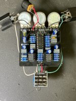
I'm building a spirit box and there is no reverb when I turn the pedal on. the LED lights, I loose a little bit of volume, but otherwise the signal is unchanged.

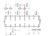
Could someone please tell help me with the signal path from the PT2399 to the Belton brick? I'm new to schematics and I think I'm getting turned around. I'm using an audio probe and I have signal from 12 on the PT2399, through R17, and lose it on the other side of R16. If I'm correct pin 3 pin on the brick is the input but there is no signal there. I may be reading it all wrong and everything I've just said is nonsense.

Thank you in advance.
 

Attachments

  • IMG_7355.jpg
    IMG_7355.jpg
    666.5 KB · Views: 20
  • IMG_7356.jpg
    IMG_7356.jpg
    686.8 KB · Views: 21
  • IMG_7357.jpg
    IMG_7357.jpg
    546.2 KB · Views: 19
No, it was a piece of fuzz. If there are and components I should test or places to confirm continuity or not, I’m open to anything. I have a case I really like made up and it would be a bummer for this to end up as a paper weight.
 
No improvement to the functionality unfortunately.
I have gone over this & can't find a fault, can you confirm that your electrolytics are the correct values, there are 2 100uf's that are different.
The 1uf, 2 . 2uF & 10uf are the same size so check those.
Can you confirm the 2 Transistors are correct?
When you do a Continuity test, you can't have the power connected!
 
Coming out of the 2399, the red is where I have signal, there is a path to ground past each of the components the signal stops at (R15, R16, C10, C11). There is a path to ground on nearly every pin of the 2399 (with the power disconnected). With the 2399 pulled there is a path to ground on 1, 3, and 4. I am really not following the circuit, its over my head, but I would love to understand as much as anyone is willing to explain (and get this pedal working).
 

Attachments

  • Spirit Box Issue.jpg
    Spirit Box Issue.jpg
    49 KB · Views: 6
Post voltages for all ICs this may indicate your problem area

As @music6000 says nothing appears to be incorrect regarding component values and orientation that we can see

The only things we can't see are the electro values which you've confirmed are correct and C9 which should have code 222 written on it, make sure that's correct because it'll obviously affect the filtering at output pin 14

Note when using an audio probe you are better to probe component pins rather than solder joints where you can, you don't always get a good connection with your probe

I'd be inclined to probe pin 5 of IC2 just to make sure you get no reverb output
 
C9 was the problem, rookie mistake of using a 2u2 instead of a 2n2. Swapped it and it is working great. I can not thank you all enough. I feel everyone gave me really solid troubleshooting steps I can use in future builds.

Also, I made an audio probe that has optional PCB test clips for attaching to component pins. It was out of convenience to hold things while I tweaked, but good to know it was also a best practice.
 
Back
Top