
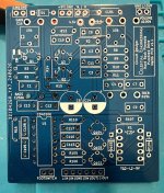
This is pedal is based on a PCB I designed myself, based on the @Chuck D. Bones-modified Animals Pedals Diamond Peak Overdrive, discussed in this thread. I call it the "Hard Rock Pinnacle Purebred Drive". As you can see, I'm late to the PCB party for this circuit. There's a good reason why this circuit has seen so many PCBs made for it: it rocks! I had been watching that thread with interest for a long time, but what finally sold me was @Brett's build report, where he said, "Think of how the Boss BD-2 responds to pick attack, now make it sound good, like really good." I have mixed feelings about the BD-2, but it's a benchmark of sorts. If nothing else, pretty much everyone and their brother has played one, so comparisons to it are a useful common ground. But I've always thought it shines particularly bright in the touch-sensitivity and volume cleanup departments. However, the BD-2 cousin, the OD-3, has been my jam for quite a while. I always wished there was a pedal that had the tone and drive sounds of the OD-3, but with the more open sound and dynamic touch-sensitivity of the BD-2. I won't say that this pedal is exactly that; in fact, the drive sounds isn't really like the OD-3 or the BD-2. But this pedal definitely has phenomenal response to pick attack and volume, and the drive sound is just great.
On top of all that - it's clearly a very flexible, tweakable circuit. I think this is a good one to breadboard and tweak values to taste. For those unaware, this circuit is essentially the same topology as the Aldrin Fuzz, i.e. Skreddy Lunar Module, Screwdriver, Hybrid Fuzz Drive, and the Skreddy/Animals Major Overdrive.
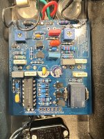
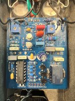
Part of the fun of this circuit is transistor rolling Q2 and Q3, which are low-gain silicon. I used metal can 2n2369 (HFE 59 per my CTT) in one build, and MPSA42 (HFE around 90) for the other. (I used 2n4123, HFE around 94, in my prototype.)
My PCB takes Chuck's effect circuit exactly; the only changes are addition of two trimpots for biasing, and an extra power supply filter cap. Additionally, I added the inverter-based relay bypass circuit I've been using for my last dozen or so builds (see my build report history - I have standalone bypass PCBs with this circuit). I also added solder holes at the bottom for traditional 3PDT bypass.
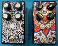
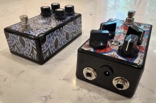
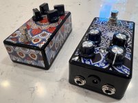
For those who watch my build reports, the exterior finish continues my recent trend of Envirotex (two-part epoxy resin) over mandala stickers. I tried something a little different this time, I made the mandala sticker cuts bigger, and didn't put the sticker on the top of the enclosure (where the power and I/O jacks are). The jury's out on this - first, this is one of my worst jobs in terms of the resin pour on the sides, and second, make the stickers bigger on the sides mean they're not as smooth, so probably more likely to catch on something and start peeling off (the resin is supposed to prevent that, but combined with a mediocre pour, it might not happen). But I'm not going to worry about it, the pedal sounds too good! (I've actually been rocking my prototype - with three of the pots wired backwards - because it sounded too good to wait on the revised PCB to come in!)
I have a few extra PCBs, I'm happy to send them out to anyone who asks.
Edit: I forgot to add in my initial post, this circuit pairs really well with the Zorkmid!
On top of all that - it's clearly a very flexible, tweakable circuit. I think this is a good one to breadboard and tweak values to taste. For those unaware, this circuit is essentially the same topology as the Aldrin Fuzz, i.e. Skreddy Lunar Module, Screwdriver, Hybrid Fuzz Drive, and the Skreddy/Animals Major Overdrive.
Part of the fun of this circuit is transistor rolling Q2 and Q3, which are low-gain silicon. I used metal can 2n2369 (HFE 59 per my CTT) in one build, and MPSA42 (HFE around 90) for the other. (I used 2n4123, HFE around 94, in my prototype.)
My PCB takes Chuck's effect circuit exactly; the only changes are addition of two trimpots for biasing, and an extra power supply filter cap. Additionally, I added the inverter-based relay bypass circuit I've been using for my last dozen or so builds (see my build report history - I have standalone bypass PCBs with this circuit). I also added solder holes at the bottom for traditional 3PDT bypass.
For those who watch my build reports, the exterior finish continues my recent trend of Envirotex (two-part epoxy resin) over mandala stickers. I tried something a little different this time, I made the mandala sticker cuts bigger, and didn't put the sticker on the top of the enclosure (where the power and I/O jacks are). The jury's out on this - first, this is one of my worst jobs in terms of the resin pour on the sides, and second, make the stickers bigger on the sides mean they're not as smooth, so probably more likely to catch on something and start peeling off (the resin is supposed to prevent that, but combined with a mediocre pour, it might not happen). But I'm not going to worry about it, the pedal sounds too good! (I've actually been rocking my prototype - with three of the pots wired backwards - because it sounded too good to wait on the revised PCB to come in!)
I have a few extra PCBs, I'm happy to send them out to anyone who asks.
Edit: I forgot to add in my initial post, this circuit pairs really well with the Zorkmid!
Attachments
Last edited:
")


