Popping Issue of M-Wave Mini Universe

slammer88

New member
I Got this m wave mini universe reverb pedal some time ago. It sounds absolutely killer, but there's a problem with that lts been there since the beginning and lots of people also experience it.

When engaged, it pops! It pops and introduces this into the reverb sound. The weird thing is, the longer the pedal stays active, the lesser this popping effect becomes when switched on and off. It makes me think of a capacitor issue, but seems like lots of people complain about it on YouTube comments. There is also a slight delay of the sound like 10-15ms.

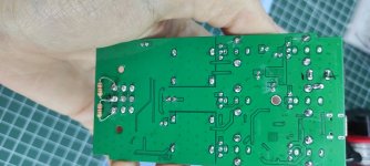
I've solved this popping by soldering 2.2k resistors from in to gnd and out to gnd on the switch, I got no tone loss, but the delay is still there. I know its pretty low, but from 500k to 10M resistors did not work at all.

I've done a video about this; I'd like to hear your opinions as well. There seems to be a weird connection of 3DPT that actually causes this popping and delay at the same time. Is there any workaround to fix this do you think?

 
Can we have pictures of the insides? Depending on the room you have to work with, it could be easy to try some solutions mentioned in this thread. A pedal that small might be a fair bit more difficult to add stuff to than a diy pedal with discrete jacks and power connectors and all that jazz.
 
Can we have pictures of the insides? Depending on the room you have to work with, it could be easy to try some solutions mentioned in this thread. A pedal that small might be a fair bit more difficult to add stuff to than a diy pedal with discrete jacks and power connectors and all that jazz.
I thought the video would be useful but there you go, it's quite a tight fit as other Chinese pedals. And it's a bit smaller 3pdt switch there compared to regular ones. Lug gaps are smaller.

I think ill remove the 2 resistors that are 22k now, as on my pedal board connected with others, they seem to lose a bit of a tone. It was good individually tho.

Another thing that caught my attention is that there are 6 or 7 polarized caps all around the circuit and all of them are 100uf/16v. It's well possible indeed, or a coincidence, but I have seen tons of layouts so far yet none of them had this much "same" valued caps. I somehow thought that would these Chinese guys go cheap and put all the polarized caps the same. Because this DC voltage accumulation on output and popping due to DC offset are seemed to somehow related to capacitors.
 

Attachments

  • IMG_20240224_093813.jpg
    IMG_20240224_093813.jpg
    209.5 KB · Views: 16
  • IMG_20240224_093740.jpg
    IMG_20240224_093740.jpg
    284.3 KB · Views: 25
  • IMG_20240224_093746.jpg
    IMG_20240224_093746.jpg
    224.7 KB · Views: 19
  • IMG_20240224_093759.jpg
    IMG_20240224_093759.jpg
    210.6 KB · Views: 12
  • IMG_20240224_094154.jpg
    IMG_20240224_094154.jpg
    276.5 KB · Views: 18
  • IMG_20240224_094146.jpg
    IMG_20240224_094146.jpg
    217.4 KB · Views: 16
Last edited:
Hello, everyone! I’ve found a solution for two of these Mini-Universe pedals for a guitarist client here in my lab.

1. I desoldered the 3PDT from the board.

2. Added 47nF film capacitors to both the Effect Input and Effect Output, underneath the board.

3. Added a 100k resistor from the Effect Output to Ground, underneath the board.

4. I cut the two spacers on the back chassis to create a little more room for the extra components; and then insulated the "floor" of the chassis.

5. Insulated the terminals of the 3PDT on the top of the board.

6. From the Input jack, I soldered onto 3PDT lugs 1 + 6.

7. From the 47nF Input capacitor, I soldered onto 3PDT lug 2.

8. From the Output jack, I soldered onto 3PDT lug 5.

9. From the 47nF Output capacitor, I soldered onto 3PDT lug 4.

10. I grounded 3PDT lugs 3 + 8.

11. Let the positive lug of the LED in the same place on the board.

12. Cut the negative lug of the LED From the board and solder it to a 1k resistor, then solder the 1k resistor to 3PDT lug 7.

13. Remove the 1k R1 resistor right below the LED; it’s a current limiter for the LED.

Leave lug 9 with nothing soldered.

This fixes the popping and eliminates the mini-delay in effect activation.

Here’s a video comparison of both pedals: Original vs. Modified.


PS: I can post a step-to-step image guide on how to do It If you guys need!
 
Last edited:
Hello, everyone! I’ve found a solution for two of these Mini-Universe pedals for a guitarist client here in my lab.

1. I desoldered the 3PDT from the board.
2. Added 47nF film capacitors to both the Effect Input and Effect Output, underneath the board.
3. Added a 100k resistor from the Effect Output to Ground, underneath the board.
4. I cut the two spacers on the back chassis to create a little more room for the extra components.
5. Insulated the terminals of the 3PDT on the top of the board.
6. From the Input jack, I soldered onto 3PDT terminals 1 + 6.
7. From the 47nF Input capacitor, I soldered onto 3PDT terminal 2.
8. From the Output jack, I soldered onto 3PDT terminal 5.
9. From the 47nF Output capacitor, I soldered onto 3PDT terminal 4.
10. I grounded 3PDT terminals 3 + 8.
11. Connected the positive lug of the LED to the same place on the board.
12. Removed the 1k R1 resistor right below the LED; it’s a current limiter for the LED.
13. I soldered the negative lug of the LED to a 1k resistor, then soldered the 1k resistor to 3PDT terminal 7.
Leave terminal 9 with nothing soldered.

This fixes the popping and eliminates the mini-delay in effect activation.

Here’s a video comparison of both pedals: Original vs. Modified.


PS: I can post a step-to-step image guide on how to do It If you guys need!
A guide would be greatly helpful indeed!
 
Back
Top