SOLVED Hydra popping

mybud

Well-known member
Ok, so this post relates to yesterday's Hydra build. You'll notice that I slightly borked the 100nF cap at top left of the gutshot.

I say this because of some weird behaviour as follows: In bypass, the LED glows dimly, which suggests TMM that it's still getting current from somewhere when it shouldn't. This is accompanied by a considerable pop when the pedal's engaged.

So question 1: is this cap related to the power supply as a filter which is now partly dysfunctional because of damage to the cap? If so, is there a simple workaround to fix this without removing the entire installation again? Reasoning immediately below.

I notice that the moar black switches don't like being removed from the housing and that there are already faint signs of wear to the switch finishes when doing so too many times. So I'm looking for a simple, minimally intrusive kludge to fix this if one of our gurus could advise. Adding a further pulldown resistor to the footswitch, or some such, if at all possible.

As in the build report, I plan to retouch one and two of the 'drum' switches, where my half-baked soldering (long layoff, chops need improving) clearly shows room for improvement. For now, I can live with the pop and enjoy the 'creative' fun aspects of the pedal but I will eventually want to fix these issues.

Thanks in advance, any advice gladly received. And please @Robert, kindly provide the schematic when time permits.
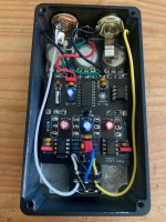
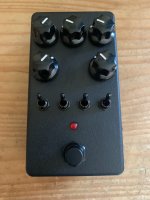
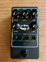
hydra_gutshot.jpg hydra_outside.jpg
 
the 100nF cap at top left of the gutshot
Sorry folks, I mean 1nF, not 100nF (same position, at top left) and this low value is probably not related to any power filtering caps in this universe. I'll check for stray wires near the footswitch meanwhile. Still puzzled that the LED shines on dimly in bypass. Never happened before, but there's a first time for everything, I suppose.
 
This is C4 whic is part of a HPF before the FV-1 so this shouldn’t effect your LED or bypass popping.

Can you send pictures from the underneath of the board? Check for solder bridges around the LED and the ground wire at the bottom of the board.
 
I notice that the moar black switches don't like being removed from the housing and that there are already faint signs of wear to the switch finishes when doing so too many times.
FWIW I've just used a black marker pen to fix the scuffs (mine are usually on the nuts), and it has worked pretty well. I assume it won't stay on well if you rub it, possibly, but I don't see that as an issue really?
 
Ok, so this post relates to yesterday's Hydra build. You'll notice that I slightly borked the 100nF cap at top left of the gutshot.

I say this because of some weird behaviour as follows: In bypass, the LED glows dimly, which suggests TMM that it's still getting current from somewhere when it shouldn't. This is accompanied by a considerable pop when the pedal's engaged.

So question 1: is this cap related to the power supply as a filter which is now partly dysfunctional because of damage to the cap? If so, is there a simple workaround to fix this without removing the entire installation again? Reasoning immediately below.

I notice that the moar black switches don't like being removed from the housing and that there are already faint signs of wear to the switch finishes when doing so too many times. So I'm looking for a simple, minimally intrusive kludge to fix this if one of our gurus could advise. Adding a further pulldown resistor to the footswitch, or some such, if at all possible.

As in the build report, I plan to retouch one and two of the 'drum' switches, where my half-baked soldering (long layoff, chops need improving) clearly shows room for improvement. For now, I can live with the pop and enjoy the 'creative' fun aspects of the pedal but I will eventually want to fix these issues.

Thanks in advance, any advice gladly received. And please @Robert, kindly provide the schematic when time permits.

View attachment 49823View attachment 49824
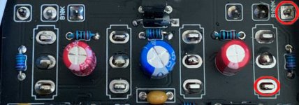
This looks like No solder on bottom toggle outlined in red, The pot outlined in Red looks like a cold joint so reflow.
The togle solder joints look cold so I would reflow all of them.
I would check all your solder joints as cold solder will cause it to pop more sooner or later.

Solder Joints.jpg
 
This looks like No solder on bottom toggle outlined in red, The pot outlined in Red looks like a cold joint so reflow.
The togle solder joints look cold so I would reflow all of them.
I would check all your solder joints as cold solder will cause it to pop more sooner or later.

View attachment 49897
Yes thanks @music6000, definitely much room for a systematic inspection and reflow. Meantime, I did rework the toggles which now function according to plan. Missed the top right pot. Thanks again.
 
Yes thanks @music6000, definitely much room for a systematic inspection and reflow. Meantime, I did rework the toggles which now function according to plan. Missed the top right pot. Thanks again.
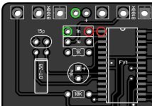
Cool, Here is a Continuity check you can do if this is the Damaged pad.
Make sure you have no power connected when testing for continuity.
This is also the best spot to jumper if no connection.
Geen circles are Ground :

Hydra Continuity Check.jpg
 
Cool, Here is a Continuity check you can do if this is the Damaged pad.
Make sure you have no power connected when testing for continuity.
This is also the best spot to jumper if no connection.
Geen circles are Ground :

View attachment 49898
If the Geen pad is bad, it just needs a jumper.
If it's the red pad, that also connects to a R3 - 1K resistor just below the 1uF Cap.
One side of the R3 - 1K only goes to C3-1uF left pad down at Pin 1 of TL072, so check for Continuity at those pads also.
 
Back
Top