RAT - What's with these filters?

jwin615

Well-known member
Been playing with the RAT. Never really paid it a ton of attention because I found in nasal but thought I could toy with the filters and find my RAT.
Well, WTF is going on here?
rat_filter_points.jpg
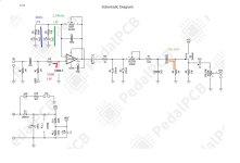
So, R4-C4 create a filter for dogs. I've found some old RAT traces that actually have C4 as 10n. 16K makes a lot more sense as a corner freq. What's the chance that someone decoded that cap wrong 20 years ago everyone has copied everyone else since?
C9-R8 copy the input HPF. Again, a pretty useless corner freq. Turbo variant used 2M2 here, because we were missing that 3-6Hz content?
I get that the green and blue filters invert and form a low cut. I've seen this explained as one being a HPF and one being a LPF in more than one place. That's incorrect. But I'm only 85% there on whats going on here. 7% of it is why? Also, Does DIST add series resistance to R3/R5(in terms of the filter)? I wouldn't think so via C5. Anyway, I'm thinking that This C3/R5 is a point of contention for me. That 1kHz nasal quality that I despise after 3 minutes of playing. Some peoples cilantro, others soap...

I feel like we could do a bit of refining on the 7Hz HPF points as well.
Does the FET need to see that high of an impedance at R9?
Anyway curious to hear others thoughts and hopefully relearn some thing I forgot from school. No thevenin equations please.
 
I'm assuming you're siming with and without the inductance of the pickup here?
That 1-2k phase shift is a pretty drastic difference between the two.

Would the inclusion of the input get not counteract the phase shift induced?
 
I don't think so. DIST just sets the feedback resistance for the non-inverting op-amp gain.

That's what I thought but wasn't sure.
Sounds likely.

I'm guessing the red filter is to reject radio interference?
Yes, but why not use a 10n and set the point at 15k? Then rfi is even more suppressed. The 308 can't even pass 15k at this slew rate.
 
  • Like
Reactions: spi
This is the best source for RAT variations if you want to check out all the ways this has been tweaked over the years by the manufacturers (and that's before us lot got started on it!):

GGBB's Multi-Rat schematic

I can't find where this was originally posted, but it's been reposted loads of places.

That R4/C4 input filter...well, if you want to stick 10n in instead, go for it. As you say, in many ways it makes more sense. You probably won't hear any difference either way, so I don't think it matters much.

The "dual leg" design on the op-amp gain stage is a good idea and has been copied lots of times since! The basic idea is that each leg sets a different breakpoint, and they're highpass filters, not lowpass (because this is feedback loop). R3/C2 limits the gain on the really low stuff, while R5/C3 rolls off the gain for note fundementals. You missed one filter too, which is the lowpass combination of C5 and the Distortion pot. That comes down in frequency as the gain (pot value) goes up, which helps tame harsh high end a bit. As does the fact that the op-amp runs out of slew-rate, aided by C6.
All that lot just sets up a vaguely bandpassed "mid forward" frequency response and adds op-amp clipping. Then come the clipping diodes.
After clipping dioes you've got the explicit tone filter of the Filter pot+R7/C8. Then there's the highpass you noted of C9/R8 which is only really a DC blocker and has no real effect on the tone (we can't hear 7Hz bass notes!). Even C10 and the volume pot add *another highpass filter, even lower.
So...yeah, there's a *ton* of filtering options in that simple circuit and you can spend plenty of time playing with them!
The big important ones are the three around the op-amp, the dual legs, and the cap across the distorion pot. The Filter control itself is variable anyway, but you can play with the response of that to get something you like. Most of the highpasses except the two in the op-amp loop are designed to be ignored (set for the bottom of the audio range or below).
 
The input of the op amp acts as a buffer (high input impedance), so there’s not interaction with the pickups.
 
Great stuff posted. I’ll add, hopefully not too redundant. ElectricDruid your site rocks, good to see you chiming in here.

The op amp input acts like a buffer (high input impedance) so we don’t have to worry about pickup interaction.

There’s a mod called the Reutz with two versions. 1. Clip out the 47R, leaving only the other filter path which is less mid forward and lower gain. 2. Replace the 47R with a 1k pot to modify this filter (or maybe add it in between the 47R and cap so you still have some R at max pot position).
 
Forgot I had this in the ol bucket of downloads. Selective memory is a helluva drug.
Thanks, I haven't seen the version with the fat rat. Will have to math that out.
The input of the op amp acts as a buffer (high input impedance), so there’s not interaction with the pickups.
Figured as much. Especially the jfet input.. but I don't understand where the 180° phase inversion is coming from in the above graphs. I'm wondering if that is what perterbs me about the stock rat tone. There's someone in that 1-2k region that is like an icepick. Like a werman fussin at ya.
What's causing this phase inversion/high peak? Wavefolding/crossover in the opamp clipping?
Also, you underlined C25(5.6n) across the output. Missed that the first time around. I haven't seen that in a RAT schem. That side of your simulation confuses me. It's been a long time since I simmed anything and have forgot most of it. What is C25 doings? Treble bleed?

@ElectricDruid that is for chiming in. Cool to see you around here.
Yeah. I left out a few filters. Was just curious about the ones notated. Want to utilize them a bit at least.
Maybe bump the 60hz in the feedback up 1-1.5 octaves and drop the 159k down to audible frequencies to maybe take some hiss.
I'm guessing we don't really worry about the phase rotation pre and post clipping. Say, I moved the 60hz filters to 180hzish, one pre and one post clipping. That wouldn't cause any resonance, would it?
 
If you connect a guitar pickup directly to the RAT (unless you enter using an additional buffer or something similar), the difference between 1n and 10n is extremely large. In addition, cable capacitance is added.

5.6n cap "imitates" Gain-Band-Width of the LM308 OP-AMP, but the simulation suggests that it is not possible.

20248k02.png
 
Interesting point, seemed like an opportunity to learn something.

I haven’t seen discussion of the pickups hitting the input HPF like this, especially considering the graph predicts such an extreme spike.

I tried guitar straight into my rat build and guitar-buffer-rat. (Toggling the buffer on and off, I’m struggling to hear much difference).

I do hear a difference when adding 10nf in parallel with C4 and the taming of the high frequencies is easily heard. But this behavior is the same whether I have the buffer on or bypassed. So I think that means this doesn’t have much to do with the pickup interaction (with my tele at least), but a 14.5kHz cutoff (1k&11nF) is audible. Maybe also since there’s some cut that occurs below the calculated cutoff frequency (since it is a curve, it starts earlier, the cutoff frequency is just where it’s starts to get really noticeable).

I’d be curious to see if others get similar results as I got with my gear (and currently testing at low volume).
Does your rat have a jfet input? I've noticed a lot of diy boards do ...
 
If it's the nasal thing which bothers you (and I can sympathise) I'd be inclined to try changing R5 to 1K. In fact I might even try that myself.
 
Back
Top