PCB Track Width

Munro306

New member
Designing my first 2 layer PCB in KiCad which will be manufactured via JLCPCB and looking for guidance on track width.
Is there a rule of thumb people use for selecting track widths? Either for power tracks or signal tracks.
I was able to find this 2015 writeup from MadBean stating:
Power traces are thicker (24mil) whereas audio traces are thin (10mil)

Is this still considered convention?

Also, how do I identify which connections (or nets) are power and which are signal?

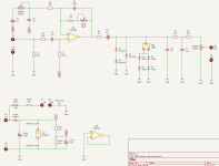
Below is my schematic, I assume the tracks for the signal connections (10 mil) are for connections on the half part of the schematic, and power tracks (24 mil) are for the connections on the lower half of the page.

1732481066654.png
 
Last edited:
Is this still considered convention?
Generally speaking, it's good practice to make sure that power traces have as little resistance as possible, hence larger traces. Lower resistance means lower heat and a happier PCB. Ground is considered a power trace and should consume as much copper area as possible to ensure the return path is as close to zero resistance as possible. Ground path is typically done with copper pours on the front, back, or both (in cases of double sided boards).

Also, how do I identify which connections (or nets) are power and which are signal?
Everything around the power section (bottom of schematic) and any direct connections to the power section (VREF flags) are power lines.
 
I use diptrace but only use the track width conventions liberally. I use 10mil for signal and will usually use 15-20mil for power but I’m never afraid to knock those down to 10mil if it makes it easier to route or if it makes for better ground pours.
 
Online calculator for current in a trace... https://www.advancedpcb.com/en-us/tools/trace-width-calculator/
Nothing on a guitar pedal is going to force you to larger traces. Even power delivery is low current but I use as big as will fit for power.
If you need high current in a trace, like in a class D power amplifier module, then certainly use the calculator. Another trick that is handy for high current lines is to leave path along the trace that has no solder mask and then solder along that path to thicken it up. I do this in my TPA3118 power amp module to get out of the tiny pins on the IC out to the larger trace. There are two output pins for each channel tied together. The light purple is where the solder mask is left out. This allows me to fully solder the pins all the way to C5 and C6 for a solid connection without relying on any skinny trace from the pins. The yellow arrows are, obviously, hand-drawn pointers to the solder mask keep-out. You can use any graphics draw for those. For the top copper in that area, I used filled zones connected to the output nets to get as much copper as I could from the pins out to C5 and C6.
1734550205662.png
 
I don't have a ton of experience, but I wanted to limit variables for my first few PCBs and just did 0.6mm for all traces and had no real issues routing or with zones being weird, even without vias. If you are limited on space or have a complex circuit, then the smaller traces for signal will of course be a great help in routing. I figured the first few boards would have enough "future things to improve on" that trace width could be one of those if I deemed it helpful
 
I like to lay mine out and check it over real good, come back to it in about 24 hours and fix the mistakes I completely missed.
I prefer to finish it as fast as possible, very late at night if possible, get the order in so that production "starts", then the next day or week review it obsessively and find out I am an idiot and any amount of patience would have prevented a lot of future-me headaches, then wait 30 days for the slowest shipping, and repeat this process as many times as I can in a calendar year without adjusting how I operate.
 
I prefer to finish it as fast as possible, very late at night if possible, get the order in so that production "starts", then the next day or week review it obsessively and find out I am an idiot and any amount of patience would have prevented a lot of future-me headaches, then wait 30 days for the slowest shipping, and repeat this process as many times as I can in a calendar year without adjusting how I operate.
Fun fact, if you contact them early enough, you can email them a fixed file. Don’t ask me how I know.
 
Back
Top