Chalumeau mods

Bricksnbeatles

Member known well
What mods are most worthwhile in your opinions? I've been looking for a cool pt2399 based effect to build for my 23rd birthday next month, and last night I settled on the Chalumeau.

First off is the matter of gain- If I understand correctly, the gain of the 386 in the circuit is 200, due to pins 1 and 8 being tied directly together. that should mean that c2 and r2 are completely redundant in this circuit, as they'll only set the gain if pins 1 and 8 aren't shorted together. c2 and r2 should give the gain of the non-fuzz version of the Clari(not) if you cut the trace between pins 1 and 8. of course, you could always cut the trace, populate r2 and c2, and connect a spst between pins 1 and 8 if you want both versions of the circuit, but why not take this in a different direction and just do a gain pot? If we cut the trace between pins 1 and 2, and then also leave c2 and r2 unpopulated, then we should be able to wire up a 1KΩ pot between pins 1 and 8 for a continuously variable gain between (I think, I'm doing mental math rn) 40 and 200. any thoughts or corrections here? I haven't double checked my calculations yet...

Next is the mater of delay feedback. more on that soon...
 
I put a clean boost on the fuzz lift switch to give it enough juice to trigger in "clean" mode. The delay feedback mod is easy, but due to the extreme pitch shifting, it is pretty much unusable as an echo.
 
I put a clean boost on the fuzz lift switch to give it enough juice to trigger in "clean" mode. The delay feedback mod is easy, but due to the extreme pitch shifting, it is pretty much unusable as an echo.
Since I plan on doing a pot instead of a fuzz lift switch, maybe I’ll just add an LPB to the front end. As for the feedback mod— unusable isn’t in my vocabulary ;) (plus with the modulation turned mostly down, it should be marginally normal)
 
Also can anyone who’s built this describe what the tracking knob does? Every demo I’ve seen adjusts at least one other knob when they adjust the tracking so it’s hard to see exactly what it does
 
Yep. Take a look at the schematic, @Bricksnbeatles. It essentially controls the signal routing to the LED, which affects the LDR tied to the DEPTH control.
Ok yeah I see, it’s sort of controlling the envelope depth, like the range knob on an envelope filter (or well, the range knob on some envelope filters, or the sensitivity knob on other envelope filters, or the depth knob on some envelope filters because sometimes range and sensitivity do other things because envelope filter parameter naming is extremely inconsistent 😂)
 
Just occurred to me I could very easily omit having a switch to remove the feedback circuit by simply modding a C50k pot to be ‘no load’.
That should free up some real estate
 
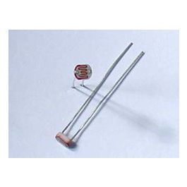
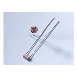
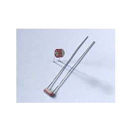
Any thoughts on which LDR is best for this circuit? I’ll probably socket it just so I can try ‘em all out, but I’m in a rush to finish this up and don’t have time to test each type out.


I’ve got about a dozen of each, so I can cherry pick the best-spec one, but not sure what range is best for the circuit
 
I put a clean boost on the fuzz lift switch to give it enough juice to trigger in "clean" mode. The delay feedback mod is easy, but due to the extreme pitch shifting, it is pretty much unusable as an echo.
Hey, I know this is old, but can you please tell me how you did this? I'm thinking of doing the same thing.
 
I've probably said it elsewhere, but the HT8970 is cool in this circuit. Lower minimum delay times, so it's a lil thicker sounding and more chorusy
 
Hi, so sorry to be necroposting but I figured in lieu of a new thread I'd ask here:

On the PedalPCB board, how would I add a gain pot? It's my first time do a mod involving precarious IC leg work.
 
If you pull up pins 1 and 8 like in this pic.
1737508102247.jpeg
Then solder either a switch that goes between open and closed and you will get a 20 gain and 200 gain setting or wire in a 1K pot and you can have a range. It’s an easy mod as the work is all done to the IC so if you mess up you can just get another as long as you use a socket.
 
Hey, I know this is old, but can you please tell me how you did this? I'm thinking of doing the same thing.
Necro'ing again to second Neil's inquiry. I'm in love with the touch-sensitive, weirdo modulation of this circuit but even with my added gain knob at zero there's some breakup/a sort of thinning tonally. Would love to just replace it with a switch that compensated for the volume loss.
 
@Manischewitz_Papi & @neiltheseal

I'd use a DPDT on-on switch (or a 3PDT if an LED-indicator is desired)

POLE 1: opens/closes the circuit between LM386's PIN-1 & PIN-8
POLE 2: switches between stock Chalumeau output to bypass and a boost placed between the main-board and 3PDT-BYPASS.

You could put the boost at the beginning, but boosting the LM386 and subsequently the PT2399... well, it just depends what you want.
BEFORE: More insanity​
AFTER: The insanity you have only louder.​

You could even experiment with putting the boost amid-ships, between the LM386 and the PT2399...


IDEA 1
I'm thinking of having a 2KNOBJOB that either controls 2 pots between pins 1&8 with one pot's switch position also having that boost at the end (so one pot from effectively pins 1&8 disconnected to a small value, the other pot a large value connected — its "min" resistance bigger than its counterpart and having pints 1&8 "connected", always)
OR
IDEA 2
4PDT 2KNOBJOB
Pole 1: connects/disconnects pins 1&8
Pole 2: CONNECTED 1&8 — VOL POT stock
Pole 3: DISCONNECTED 1&8 — 2nd VOL POT met Boosht
Pole 4: LED indication


If'n' going totally insane, that POLE 1 could still be used to switch out connected/disconnected WITH the IDEA 1 intact, so IDEAS 1 & 2
28d3f1edb078caa28f19f77f8307f19a.gif


LOOK!
OVER THERE!
IT'S A CIRCUIT-BOARD...
IT'S A GROUND-PLANE...

NO! ONCE AGAIN, IT'S BREADBOARD BLOKE!


breadboard-bloke-jpeg.59359
 
@Manischewitz_Papi reached out for guidance on this, so I slapped this together and made a couple little snippets of a clean Chalumeau.

Using the JFET buffer, as the next cleanest preamp board I have on hand is the OD-1.
Input goes to the buffer which has it's output split - one side going directly to one leg of C2 (which has been lifted from the board), the other to the board input. PT2399, but I'll whip up some clips with the HT8970 once I settle on a preamp

First clip is with pins 1&8 installed, second clip has them lifted

I prefer the feel of the pins lifted, but both gain modes offer a good amount of fun
With the input being split, you can also add sidechain input for the envelope.

The JFET buffer board used doesn't get up to unity, so I'd recommend another preamp in it's place
 
Couple more snippets, this time with a SHO input. The 386 input is coming directly from the guitar. This brings it up to unity gain, and slightly louder with some dirt in the highest gain settings


Pins lifted -

Pins inserted -
 
Couple more snippets, this time with a SHO input.


I like the sho in that spot, how may parts is in that build? Also do you happen to have a have a lpb1 to try in that position? im sure it would get the job done too.

I find the wackyness of the clarinot can be damn fun but also overwhelming at times. Its sounds pretty great with the modulation down low too. Also handles hign gain being feed into it very well. Im running a glory hole + odr1 into it and im getting some great 80's hair metal solo sounds from my princeton
 
I find the wackyness of the clarinot can be damn fun but also overwhelming at times. Its sounds pretty great with the modulation down low too. Also handles hign gain being feed into it very well. Im running a glory hole + odr1 into it and im getting some great 80's hair metal solo sounds from my princeton

I love finding the sweet spot with the depth cranked, just enough delay, and tracking fairly high up so I can play softly without much change but digging in is accentuated by the trippy wow/flutter. I really just want a unity gain, totally clean version of this circuit because I have my dirt needs amply covered in my setup.
 
Back
Top