aion
Authorized Vendor
(Adapted from this thread)
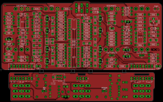
About four years ago I took a shot at the Roland Jet Phaser:

The first prototype sounded great. I was about a week away from releasing it when I decided to build a second prototype just to be extra thorough... and with no obvious differences in the build, this one had the dreaded "thunk" at the bottom of the sweep that has plagued pretty much all DIY attempts over the past two decades, e.g.:
If I biased it so the "thunk" was gone, then the phase was too weak and it didn't sound anything like the original.
It got bumped from the release schedule until I could spend more time with it, and somehow four years have gone by. I may be able to get to the bottom of it eventually, but it's been a very hectic year with (waves hands in the general direction of Washington, D.C.) and I can't give it much direct focus for the time being, certainly not for the next few months.
If anyone wants to take a stab at it and discuss their findings in this thread, I have PCBs that I would be happy to send out for free. I have a full build doc, schematic, etc. as well as JFET data measured from four different vintage units (I managed to accumulate three of my own during the development process). I can also supply matched octets of 2SK208-Y JFETs on SMD adapters along with the boards, so it cuts out the most annoying part of the build.
I dug deep into the archives on this one and I don't think I found any reports of a successful DIY build of this circuit, and so it was a bit Ozymandiesque of me to think I could tackle it... but if we can figure out on a technical level where the thunk comes from, and we crack the circuit in a reliable, repeatable, and public way, then the whole DIY community benefits.
Note: I have around 12 prototype boards available and 8 are already claimed, so I'll be a bit more selective on the last four, but if you have a strong electronics background (particularly theory) and a good understanding of the technical concepts of this circuit, and a willingness to volunteer some time for Science™, then send me a PM.
I'll follow up with all the research I've gathered on this circuit so we can all start from the same place.