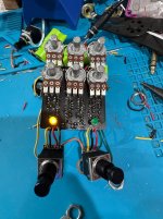
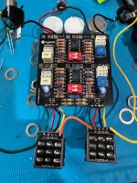
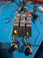
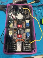
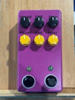
I’ve finished the mini KoT and it sounds great but I can’t get the right LED to work. I’ve pulled it out of the enclosure and am testing just the board plugged in. Replaced the LED and no luck. The 4k7 LDR seems to look fine. Any thoughts on what gives?
Very good point. Ok, how do I check continuity between the 3pdt and the LED? I’m assuming one point goes to the anode (+) side of the LED lug and one goes to a 3pdt lug? It looks like LUG 3 on a 3pdt is usually the LED signal? I’m using a PedalPCB daughter board too.
Very good point. Ok, how do I check continuity between the 3pdt and the LED? I’m assuming one point goes to the anode (+) side of the LED lug and one goes to a 3pdt lug? It looks like LUG 3 on a 3pdt is usually the LED signal? I’m using a PedalPCB daughter board too.
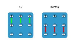
Check the switch first. Get your digital multimeter and put it in continuity mode. It usually has a little icon on it that indicates that it is going to make noise when it detects continuity.
In the on state:
There should be continuity between lugs 1 and 2, and they should not have continuity with lug 3.
There should be continuity between lugs 4 and 5, and they should not have continuity with lug 6.
There should be continuity between lugs 7 and 8, and they should not have continuity with lug 9.
In the bypass state:
There should be continuity between lugs 2 and 3, and they should not have continuity with lug 1.
There should be continuity between lugs 5 and 6, and they should not have continuity with lug 4.
There should be continuity between lugs 8 and 9, and they should not have continuity with lug 7.
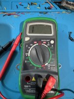
I think my DMM is broke. I turned to what I’m pretty sure in the continuity tester. No beep when I touch tips together. No continuity on the switch that does work either so I think my DMM might be broke some how. Any thoughts?
I think my DMM is broke. I turned to what I’m pretty sure in the continuity tester. No beep when I touch tips together. No continuity on the switch that does work either so I think my DMM might be broke some how. Any thoughts?
Not all DMMs have a beep function, but that looks like it would be one to me.
Could you have a bad probe? Do other functions work?
In a pinch you could click over to the left and measure the resistance in ohms - no continuity expected on the switch = infinite ohms, continuity expected = some small number (similar to what you would measure touching the probes together.)
Ok. I bought a new pair of wires and that helps. Now I get a beep on one of my DMM’s lol. Now after checking both the left 3pdt that works for the LED and the right side that the LED doesn’t work, both switches are showing continuity where they should and shouldn’t be.
The other bizarre thing I realized just now testing it again is that both sides control the other side in terms of pots. So when you turn on the left channel (top row of pots), the bottom pots for the other side also work!?! Something is amiss. Any ideas how to trouble shoot what is going on with the pots. And the bottom row also controls the top.
I tried to attach a video of it but it’s too large. But the bottom line is that either side controls the other side as well. And even in bypass, the gain, volume and tone pots work.
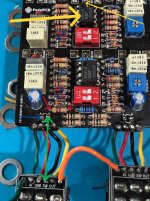
There should be continuity between the points indicated by the green double arrow.
There should not be continuity between either end of the green double arrow and the blue arrow.
There should be continuity between the solder pad indicated by the blue arrow and only one end of the resistor indicated by the red arrows. There should not be continuity between the blue arrow and the other side of that resistor (the other red arrow). Try to get your probes on the leads of the resistor when checking continuity to it, and not its solder pads.
There should not be continuity between the red arrows. (You'd probably notice the LED blow if there were.)
Assuming every thing has checked out so far, remember which side of the red-arrow resistor did NOT have continuity to the blue arrow, because you're going to check the continuity between it and one side of a diode that's not visible in the photo next.
The thick yellow arrow points to an opamp that's hiding the diode you want to check. The thin yellow arrow points to where it will be, between the opamp and the center pot at the top of the board.
Check continuity between the left (un-striped) side of that diode and whichever side of the red-arrow LED you were remembering from above. There should be continuity there.
* * *
If the above continuities check out, get another LED soldered in there (mind the polarity), connect it to your power supply, and poke around the parts you just checked the continuity of with a wooden chopstick or some other similarly shaped object that doesn't conduct electricity. You're checking for bad solder joints here. Watch for the LED to light up while you're poking around at the components. When/if it lights up, you'll know that you need to reflow the solder at that joint.
Thanks so much everyone on helping out. I checked continuity as GenXSlacker suggested and it passed all tests.
I replaced the LED and sure enough, it came on this time. However, after switching it on and off a few times, the LED went out again. I figured it was a wiring issue with the daughter board and I was right. The ground and switch lugs barely had any solder on them. That fixed the LED issue for good AND also fixed the pots working at all times issues.
Now both LED’s work and the footswitches independently turn off and on FX! Success!
Just when you thought it was over. I had both channels and LED’s working so I went to box it up. Was having grounding issues with the input jacks so I loosened them and rotated them a bit so the tabs wouldn’t hit the lid. Now the right side (top pots) don’t work. And the right channel can only be faintly heard when the left channel is engaged. When solo, the right channel doesn’t work at all.
Any ideas what is wrong? I pulled on various wires to test for bad solder and one of the ground jack wires to the input made some cracks and sound would pass thru for a second. I’ll try reflowing that and see if anything helps.
I pulled on various wires to test for bad solder and one of the ground jack wires to the input made some cracks and sound would pass thru for a second. I’ll try reflowing that and see if anything helps.
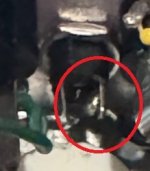
dc jack ground leg kinda looks like the solder didn't take. maybe this is what you meant though
probably wouldn't cause those symptoms but might be worth reflowing if it looks/feels loose in person
Just when you thought it was over. I had both channels and LED’s working so I went to box it up. Was having grounding issues with the input jacks so I loosened them and rotated them a bit so the tabs wouldn’t hit the lid. Now the right side (top pots) don’t work. And the right channel can only be faintly heard when the left channel is engaged. When solo, the right channel doesn’t work at all.
Any ideas what is wrong? I pulled on various wires to test for bad solder and one of the ground jack wires to the input made some cracks and sound would pass thru for a second. I’ll try reflowing that and see if anything helps.
Ok I solved it once and for all. When I took the. PCB out of the enclosure, a wire from the daughter board to the PCB had snapped. Quick solder and she’s good to go!
Thanks (again!) everyone for the help!
Now I just need some green KN1250 knobs for the top row and I’ll be set.