Mini KoT no LED

Jbanks

Active member
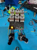
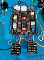
I’ve finished the mini KoT and it sounds great but I can’t get the right LED to work. I’ve pulled it out of the enclosure and am testing just the board plugged in. Replaced the LED and no luck. The 4k7 LDR seems to look fine. Any thoughts on what gives?

Thanks in advance!
James
 

Attachments

  • IMG_1184.jpeg
    IMG_1184.jpeg
    767.3 KB · Views: 17
  • IMG_1185.jpeg
    IMG_1185.jpeg
    772 KB · Views: 17
Very good point. Ok, how do I check continuity between the 3pdt and the LED? I’m assuming one point goes to the anode (+) side of the LED lug and one goes to a 3pdt lug? It looks like LUG 3 on a 3pdt is usually the LED signal? I’m using a PedalPCB daughter board too.

Thanks
James
Check continuity on the switch. It doesn't really take all that much heat to damage a stomp switch
 
Very good point. Ok, how do I check continuity between the 3pdt and the LED? I’m assuming one point goes to the anode (+) side of the LED lug and one goes to a 3pdt lug? It looks like LUG 3 on a 3pdt is usually the LED signal? I’m using a PedalPCB daughter board too.

Thanks
James

Check the switch first. Get your digital multimeter and put it in continuity mode. It usually has a little icon on it that indicates that it is going to make noise when it detects continuity.

3PDTcontinuity.png

In the on state:

There should be continuity between lugs 1 and 2, and they should not have continuity with lug 3.
There should be continuity between lugs 4 and 5, and they should not have continuity with lug 6.
There should be continuity between lugs 7 and 8, and they should not have continuity with lug 9.

In the bypass state:

There should be continuity between lugs 2 and 3, and they should not have continuity with lug 1.
There should be continuity between lugs 5 and 6, and they should not have continuity with lug 4.
There should be continuity between lugs 8 and 9, and they should not have continuity with lug 7.
 
I think my DMM is broke. I turned to what I’m pretty sure in the continuity tester. No beep when I touch tips together. No continuity on the switch that does work either so I think my DMM might be broke some how. Any thoughts?

Thanks
James IMG_1346.jpeg
 
I think my DMM is broke. I turned to what I’m pretty sure in the continuity tester. No beep when I touch tips together. No continuity on the switch that does work either so I think my DMM might be broke some how. Any thoughts?

Thanks
JamesView attachment 120140
Not all DMMs have a beep function, but that looks like it would be one to me.

Could you have a bad probe? Do other functions work?

In a pinch you could click over to the left and measure the resistance in ohms - no continuity expected on the switch = infinite ohms, continuity expected = some small number (similar to what you would measure touching the probes together.)

The beep function is very handy though.
 
Ok. I bought a new pair of wires and that helps. Now I get a beep on one of my DMM’s lol. Now after checking both the left 3pdt that works for the LED and the right side that the LED doesn’t work, both switches are showing continuity where they should and shouldn’t be.

The other bizarre thing I realized just now testing it again is that both sides control the other side in terms of pots. So when you turn on the left channel (top row of pots), the bottom pots for the other side also work!?! Something is amiss. Any ideas how to trouble shoot what is going on with the pots. And the bottom row also controls the top.

I tried to attach a video of it but it’s too large. But the bottom line is that either side controls the other side as well. And even in bypass, the gain, volume and tone pots work. 🤷‍♂️

Thabjs
James
 
Back
Top