Dual Seabed delay ?

The Gator

Well-known member
Anybody already make a dual Seabed delay already?
I was thinking after a gig last week that I would like two delay pedals on my gig pedal board. One for a good slapback, the other for longer, more saturated delay.
I could just make another magnetron. But then I thought about making a dual delay in one 1590BB2 would be great. Even more interesting would be a series/ parallel switch to get a little crazy with it.
I like the magnetron a lot. The Seabed seems similar but simpler. Smaller footprint and only 3 pots. 2 of them in a 1590BB2 might be pretty tight, but would save space on the pedalboard. Any thoughts would be appreciated.
 
Are you thinking 2x Seabed pcbs (probably only fits in 1590XX) or a custom pcb (could probably fit 2 seabed circuits in 1590BB).

Another way to tackle this could be in digital (FV-1, DaisySeed). I think with filtering inside the algorithms you can get very much in the ballpark of the magnetron or seabed. Pt2399 isn't really "analog delay" anyway so you aren't sacrificing that specialness. This would allow a row of knobs for each "preset", and you can switch between presets. Either in a 1590BB with 2 stomps (on/off, preset), or 125B with one stomp that cycles (off-mode1-mode2-off-etc.)

I'm getting up to speed on Daisy (used FV-1 forever but it's limited for this kind of thing). Others here are more advanced on Daisy, but I'd still be down to work together on a project like this.
 
I like the simplicity of the seabed. Time, level and feedback. I know nothing about Daisyseed.not much about FV-1.
I would be awesome to have a custom board designed for a dual delay with a built in series/parallel switch. Not sure if there is enough interest for a circuit layout designer to invest the time?
I like the idea of series or parallel, and a footswitch for each circuit.
 
For parallel mode, you’d want the 2 different delays mixed together, right? I guess you could use Seabed pcbs and do a blender circuit, but that would result in 2x the dry signal in some cases (I think). Better to mix Dry + Wet + Wet all together at once (IC1.2 pin6).

IF you’re ok with Buffered bypass, then I think this could be done quite elegantly with 2 lightly modded Seabed pcbs, or a custom pcb that combines only the needed items.

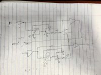
Here’s a rough block diagram. The dry signal is always going thru both Op Amps, hence “buffered bypass”.

Edit - this schem won’t work because delay2 output feeds directly back into delay2 input
 

Attachments

  • IMG_0822.jpeg
    IMG_0822.jpeg
    349.6 KB · Views: 9
Last edited:
Alternately, the whole thing could probably be built on a Terrarium pcb with Daisy programming. The enclosure size would then just depend on how much foot space you want.

One drawback of the Terrarium PCB is the digital dry through. But, that could be bypassed with a small daughterboard incorporating an Op amp mixing stage (like all the ppcb FV-1 designs have). Not that I can hear that the Daisy is digital dry at all… just the principle of it.
 
I'm thinking of doing two of them in one enclosure for the same reason - two different delay times. The way my pedalboard is set up I'd put them in a 1590bx2, but for a normal kind of pedal, you could order a 1590q from hawk electronics and fit both boards into that. A 1590q is like a square 1590bb so you have space for the jacks and footswitches. You may be able to get them into a horizontal 1590bb but it might be tight. Check the measurements and see if you can fit it.
 
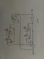
On second thought, that block diagram I posted wouldn’t work. I think this one would (still buffered bypass)
 

Attachments

  • IMG_0830.jpeg
    IMG_0830.jpeg
    542.3 KB · Views: 11
If you wanted to really shrinkify, I think a dual seabed would be doable as a SMD layout in a 125B with dual footswitches (left feeds right, each individually toggled). Since there are only 3 controls per side, the 6 controls aren't too overwhelming. You could probably go nuts an add a seventh control to sum the outputs and run them in parallel instead of series.

I have one on a 45mm x 55mm PCB with lots of room to spare, so stretching two of them to the insides of a 125B would (probably) be a piece of cake -- especially since I think a lot of the electrolytics I have on there are overkill and could be MLCC instead.

 
FWIW.. I think the seabed sounds pretty dang cool for a basic "Analogish' " delay... 2 in one box is pretty simple no fuss solution.
 
For this build I used the FV-1 Only for generating repeats, and rebuilt the rest of the circuit (filters, feedback) in analog.


Not sure how much it helps, but a single Fv-1 could handle the repeats for both delay lines if the project got more custom.
 
I just received to seabed delays from Robert. I'm going to build two of them as circuit boards for now and just make sure I like the way they sound and do a test with them in parallel and see what needs to be done to modify. I'm pretty sure I can squeeze two of them into a 1590BB2.
I don't plan on making a bunch of these. I just want something for our gigs that's quick and easy to change my sound. If I can figure out how to simply run them in parallel that's just a bonus. I want it set up to where each one has their own switch to turn it on or off. If both of them are on, they will naturally be in series. First one set short second one set long. I'm putting one together as I type...
That would be really cool to have one circuit board that was designed to be a double delay and fit in a 1590BB2. I imagine there has to be some sort of either tone control or dry signal control if they're both running parallel, but we'll see.
 
Phi1, with the fv1 design to make a dual delay, is the signal path still basically analog? And the repeats are digital from the fv1?
In my build, the dry is all analog. It's basically identical to the seabed dry path except:
-I added a non-inverting buffer stage first (the inverting boost stage doesn't have as high input impedance... may not matter since delay is usually later in the chain so you probably have a buffer somewhere).
-I made the first inverting stage unity (Seabed is 2x). I didn't want to risk clipping the FV-1 (which is 3.3V instead of pt2399 5V)
-I made the 2nd inverting stage (mixing op amp) unity (Seabed is 0.5x, to reduce pt2399 noise).

The wet signal follows the same analog filters as the Seabed, and uses the FV-1 as a replacement for the repeats engine of the pt2399. Very simple code (write to the delay head, read the time pot and map it to a delay address, output the delay). It's actually a bit more involved since I added the modulation inside the code.

The PT2399 has several op amps packaged within it, for you to use, and you access them with the pins 9~16, and you see the Seabed has resistors and capacitors to make filters using these op amps. So I had to follow the PT datasheet (and electrosmash article was helpful) to place separate op amps in my circuit.

So the PT2399 is a digital repeats engine. The FV-1 is a digital repeats engine, but much less noisy. The PT2399 has a reputation of being analog-ish because people filter it to reduce the noise. I've applied the exact same analog filters (best I could tell).
 
So finish building two of them and made some special wiring harnesses to attach to the breadboard so that I could easily wire them parallel to each other. Which they really don't sound bad at all paralleled. It sounds very similar to being in series except you can tell the difference the first repeat is not getting doubled yet again by the second delay circuit.
However, if you are in parallel you turn one of them off, you are essentially shorting the in and out together for the other one that's left on and it goes into instant rapid oscillation. Not really a deal breaker for building it with a parallel switch but I need to figure out some fancy wiring.
 
So putting both of them in parallel, if you put one of them in bypass, it starts to feed back because it's true bypass. You've essentially connected its own input to its own output and it starts to oscillate. Flipping the switch back to series stops it or putting the other circuit back in. There's no reason to have a parallel switch turned on if you don't have both delays on so it kind of doesn't matter.
The other option would be to have two contacts on the same switch that break open the true bypass on both of them. This would not allow them to oscillate if one of them is off. However it will cut the signal completely passing through.
So basically to keep it this simple I would have to make a choice. Either run into potential oscillation because I forgot both have to be on when you flick the switch to parallel, or run into a different troubleshooting problem when you don't know why you have no signal getting through. You would simply have to make sure both delays are on if the switch is set to parallel. Clear as mud
 
Soft switches to an ATTiny24, which controls all the logic and uses relays as the switches could work.

Otherwise
I think the main idea could be that instead of the stomps being try bypass, they just cut the delay signal

By the way, for parallel, how are you mixing the signals? Just tying the outputs together? Which would means it’s using the R6s as passive mixing resistors? Including a buffer mixer stage could fix the oscillation
 
Yes these first tests are just straight crude and simple. The inputs are just tied together on the breadboard to a jack. So are the outputs. It only oscillates when you put one of the two in bypass mode. But there's no point in even being in parallel if you don't have them both on. The whole test in the beginning was just to see if it was worth bothering with parallel. I have to say it does sound better in parallel if you're going to use two different delay signals
 
"I think the main idea could be that instead of the stomps being try bypass, they just cut the delay signal."

That is an interesting idea. Please elaborate.
 
So if you break the delay path (switch before or after R15 or C14), the delay sound can’t get to the mixer (IC2.2), so you’ll just have analog dry.

If you use a stomp to cut the delay, then you’ll have buffered bypass instead of true bypass. But I think it’d solve the oscillation feedback, since both pedals will be ON, just one of them won’t that the delay signal mixed in.
 
TL072 minimum output load is 2k ohm. So with your R6 (1k) acting as mixing resistors, I think that’s at the limit. If circuit A is at zero output, then circuit B sees 2k ohm load into GND, essentially). So we’re right on the edge of what’s allowed. I’d say bump those R6 up to 10k, and the R22s up to 100k, to be safer. Or use an active mic stage
 
Back
Top