jessenator
Well-known member
Beyond that, if there's not that convenience of already having that spare part, so to speak, is it a general good idea to go out of the way to implement?


This is the thread that raised my question in the first place since it makes the AionFX versions the opposite of the original pedals and every other clone. My question is not resolved in that thread and still hasn't still hasn’t been answered.This thread might give you answers or at least clues.
Hello!
Recently put together this Big Cheese and noticed that the Mode switch was acting odd, until I realized that the order of the modes were reversed to what I was expecting! The original Big Cheese has the cheese mode on the far left and the tone bypass on the far right so I figured it would be the same here. Unfortunately, AionFX doesn't provide switch position labels in their documentation so I don't know if that is intended. It seems more likely that I buggered up something to cause the order of the 3P4T selection to be reversed. So, my questions:
- Has anyone built this before...
- fydo
- Replies: 3
- Forum: Troubleshooting
hey look! verification of what I just posted. might as well get flagged for unsportsmanlike conduct since football is back ...
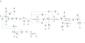
the six connections between the rotary board and main board in no particular order ...
one has continuity to ground (pole c)
one has continuity to the middle lug of the tone pot (throws A1-3)
one has continuity to D2 (pole B)
one has continuity to C11(pole A)
one has continuity to C9 (throws B1-2)
one has continuity to R8 (throw C1)
It's like they included a schematic for a reason.


I think they are trying to verify that clockwise counts up and not downit's going to be super relevant since the needed switch is a 3P4T
let's end the day on this. there's only four throws which means that the switch only has four positions. if you've been told that cheese mode is position 1 and you've been told that position 4 is off and that the rotation is clockwise then there's nothing more to figure out here.

heheheI'm designing the artwork, but I can't get a clear answer on which direction the 4 modes on the rotary switches are ordered. I've asked Aion but haven't heard back and there doesn't seem to be a clear answer among the build reports and forums posts. Can anyone whose built these circuits confirm if this is the right order or if I need to reverse my labels?

awww we're deleting posts now.

That would be greatly appreciated.
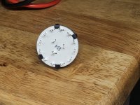
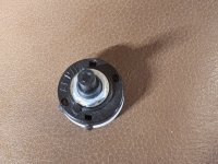

 ...
...
Ah dangI was mistaken, I actually ordered the 3P4T switch.
 . I bit the bullet and ordered two of the 3p4t rotary switches from stomp box parts. I'll solder them in and continuity test when they arrive. Thanks all.
You can do a lot of continuity testing before you get them though.Ah dang
Yeah, I think I have a good handle on the six daughter board connections. I'll do the same for the Obelisk and probably try to put all the stuff from my notes in a build report when it's all buttoned up. The black box is Aion's schematic labeling. There's evidence that schematic ABC1 is full-CW on the rotary (that would match the original pedal and the 1,2,3,4 labeling on the picture of his demo build), and evidence that ABC1 is full-CCW (troubleshooting reports and best guesses from the rotary data sheet).You can do a lot of continuity testing before you get them though.
Map out where 1-6 go and get aquainted with the schematic-pcb interaction.
| Header | Net |
|---|---|
| H1 | C9 |
| H2 | C Common |
| H3 | C11 (tone / recovery side) |
| H4 | Tone pot wiper |
| H5 | Ground (pad A) |
| H6 | R8 / rotary hole 1 |
| Full CCW outer pins | 1 click CW outer pins | 2 clicks CW outer pins | 3 clicks CW (Full CW) op | |
|---|---|---|---|---|
| 12 o'clock common | 5:30 | 4:30 | 3:30 | 2:30 |
| 4 o'clock common | 1:30 | 12:30 | 11:30 | 10:30 |
| 8 o'clock common | 9:30 | 8:30 | 7:30 | 6:30 |
| Click | Mode |
|---|---|
| Full CCW | Cheese |
| 1 click CW | Scooped Mids (1) |
| 2 clicks CW | Flat Mids (2) |
| Full CW | Off |