5 Way Splitter - Advice Needed

Hey folks, so I'm building a 5 way splitter using the JFET buffer boards. But I have a question as to the best way to parallel them. I'll mostly be using it during re-amping but could occasionally plug my guitar straight into it. Secondary question I guess but I have a bunch of 2N5458s. Is this a suitable JFET for the job?

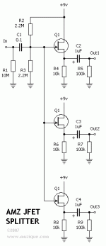
I'm guessing I don't want the signal going through the input impedance resistors 5 times after the split. So should I send it through the input resistors once and then parallel from there? I guess my question is which pin on the JFET board will allow me to insert the signal at the right point similar to this AMZ design.

split1.gif
 
The J201 and 2N5458 have different ranges of the Vgs(On), Vgs(Off) and Idss specs so some re-biasing may be required. Check the datasheets for each and compare.
 
For the design above you can omit the 100n and 2M resistors from all but one of the buffer PCBs.

What I would probably do is install one of the 2M resistors on one of the boards, and the other 2M on one of the other boards. This will give you a free pad to connect your wiring without having to make any nasty jumpers.

The red pads in this image are your connection points to the Gate of the JFET. They're all connected together.

1660826663200.png
 
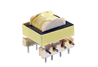
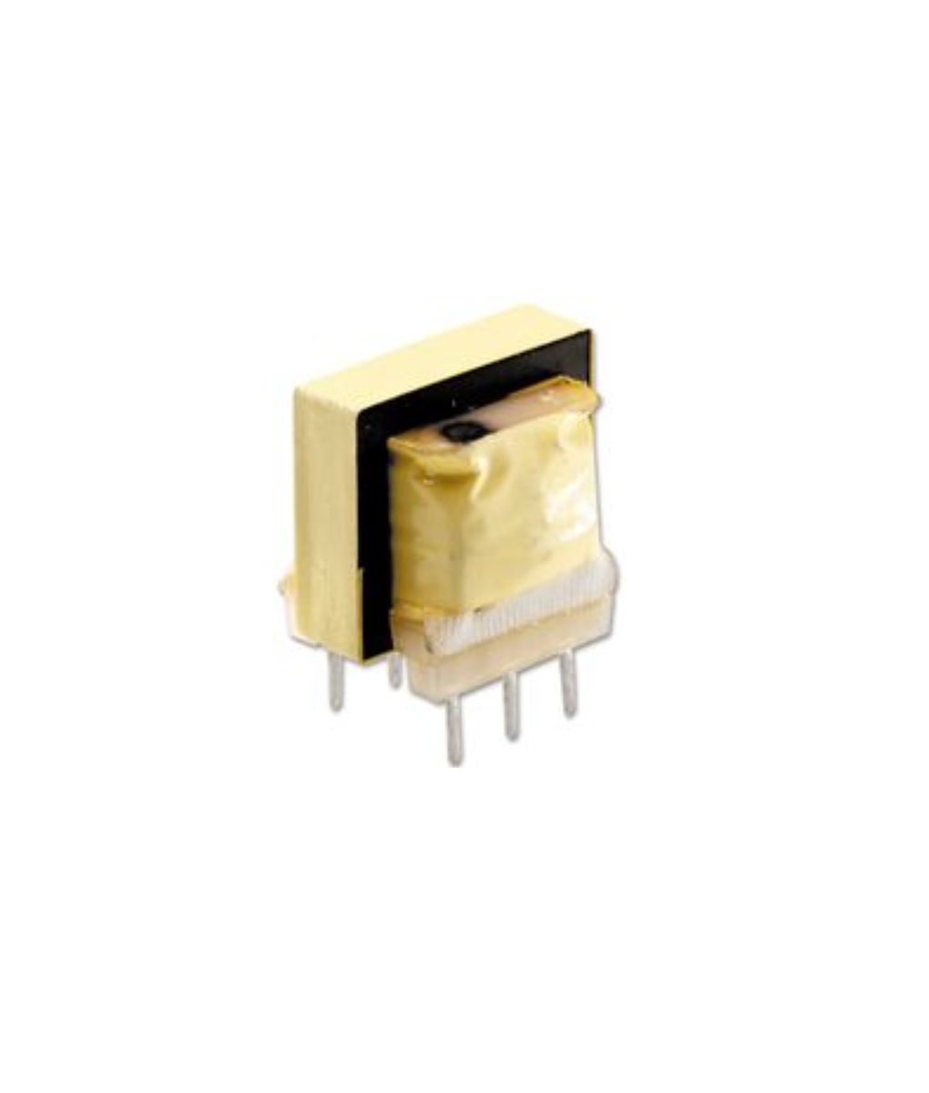
Check out the specs on the TY-250P

It's got a broader frequency-range than the TY-141P if you want to use your circuit on bass, keys etc.

The nicest thing about the TY-141P is that you don't have to go far to get it:\
 
  • Like
Reactions: fig
Check out the specs on the TY-250P

It's got a broader frequency-range than the TY-141P if you want to use your circuit on bass, keys etc.

The nicest thing about the TY-141P is that you don't have to go far to get it:\
Will the 600ohm impedance be an issue for the 250p going into pedals, amps etc?
 
  • Like
Reactions: fig
I guess to try and make things clear I'm trying to make a 4 out, 4 in box for re-amping with multiple distortion pedals or amps at once. The box will have a transformer isolated XRL-re-amp in which will feed a Box and All circuit for level and EQing, which will feed the 4 JFET splits which will have a transformer isolated out each.

A separate set of transformer balenced/isolated returns will feed my interface on the way back in.
I can get this locally, so was thinking of using it for all the transformers. I figure the pedal returns don't need to see a high impedance so no need for the expense of a full DI transformer, the original guitar DI will have gone through one of those already.

Was thinking of housing the whole thing in a single 1590DD.

1663140609514.png
 
Will the 600ohm impedance be an issue for the 250p going into pedals, amps etc?
Not to be impudent, but what's "impedance".

Kidding, sort of. Impedance is something I'm still trying to figure out because it involves <gasp> math. Even with the aid of online calculators I think I still mess up when trying to figure it out. So please forgive my ignorance when I ask:

Could you put the transformers before each of the JFETs?


PS: The transformer you linked to looks interesting, but it is a few clams more dear than the 250p which would add up quickly if you were making a bunch of your splitters. — I shall compare their specs further, thanks for the link.
 
Last edited:
Not to be impudent, but what's "impedance".

Kidding, sort of. Impedance is something I'm still trying to figure out because it involves <gasp> math. Even with the aid of online calculators I think I still mess up when trying to figure it out. So please forgive my ignorance when I ask:

Could you put the transformers before each of the JFETs?

Basically the load/resistance encountered by an electronic signal. Guitar signals expect to see a high impedance, sometimes as much as 1M Ohm or more, otherwise parts of the spectrum can be shaved off.

I think the issue with putting the transformers before the JFETs is that you won't achieve true isolation because the output will still share elements of the circuit. However I think the TY-250p you linked to will be fine because the re-amped signal will see the right impedance either from the Box and All or from the JFET buffers. The subsequent pedals will be fine with the signal that comes out of those transformers. It may all seem like overkill but when re-amping all the noise starts to add up without isolation.
As for the returns, again because they are from pedal outputs, and not the guitar itself the crazy expensive high impedance transformers used in passive DIs won't be needed, they purely will be performing balancing and isolation.
 
For the design above you can omit the 100n and 2M resistors from all but one of the buffer PCBs.

What I would probably do is install one of the 2M resistors on one of the boards, and the other 2M on one of the other boards. This will give you a free pad to connect your wiring without having to make any nasty jumpers.

The red pads in this image are your connection points to the Gate of the JFET. They're all connected together.

View attachment 30900
I don't suppose you'd have time to look over my passive isolation/balancing circuit? I'm still trying to wrap my head around transformer windings and pin outs. 1663321762689.png 1663321738167.png
 
I guess my other question is, Mouser has a range of Hammond transformers, I'm using their direct box one to make my passive DI box. They have some reasonable priced ones, but the response tends to be 150hz+. How much roll off actually is there below that range typically? Guitar doesn't need a whole lot below that anyway normally. I think I'd tend toward getting a decent Re-amp transformer but post buffer the TY-250p should be fine I reckon, maybe over time I can upgrade them.
 
Back
Top