djmiyta
Well-known member
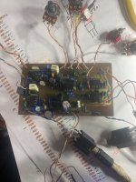
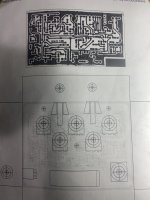
This time I used Madbeans layout. Its the furthest I’ve gotten on this monster. I am now signal tracing it and get signal up to and out the gain pot.
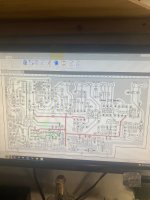
I had a couple small bridges to fix and found that R7 is either 150 ohm or a 10M neither is correct should be 100k which I have not fixed yet as I caught it just now.
Also I originally plugged in 9 volts instead of 18 volts noticed the regulator got real hot real fast ( which to me was odd) and once 18 v was plugged in no more heat but I’m wondering if I possibly fried a tranny but I’m getting 15.6 volts everywhere I should be and I would’nt think that would damage anything but I know jack shit so I’m hoping any one of you way smarter people can see something I’m not . I’ve NEVER had a more pain in the ass build and now it’s become personal one way or another I will build me a working Openhaus.
I subbed a J201 in for the 2n5457 cause I was lazy and did’nt want to hunt for one ( seeing that they seem interchangeable in a lot of pedals
I’m hoping the pics are clear enough .Has anyone else here successfully built one?
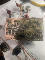
And lastly I know the board is a bit rough but Ive etched hundreds of boards the same way for years and have NO problems with the boards unless I physically leave a trace out or something which I can normally repair in someway I say that only cause I ve seen the incredible work done by a lot of people here and figure we could wait on opinions of how the board looks UNLESS you spot something that would make this not work then Im all ears
This has been an awesome forum and I love coming here and reading about the problems and solutions so thanks to any and everybody who takes their own time to read this and check it out
I had a couple small bridges to fix and found that R7 is either 150 ohm or a 10M neither is correct should be 100k which I have not fixed yet as I caught it just now.
Also I originally plugged in 9 volts instead of 18 volts noticed the regulator got real hot real fast ( which to me was odd) and once 18 v was plugged in no more heat but I’m wondering if I possibly fried a tranny but I’m getting 15.6 volts everywhere I should be and I would’nt think that would damage anything but I know jack shit so I’m hoping any one of you way smarter people can see something I’m not . I’ve NEVER had a more pain in the ass build and now it’s become personal one way or another I will build me a working Openhaus.
I subbed a J201 in for the 2n5457 cause I was lazy and did’nt want to hunt for one ( seeing that they seem interchangeable in a lot of pedals
I’m hoping the pics are clear enough .Has anyone else here successfully built one?
And lastly I know the board is a bit rough but Ive etched hundreds of boards the same way for years and have NO problems with the boards unless I physically leave a trace out or something which I can normally repair in someway I say that only cause I ve seen the incredible work done by a lot of people here and figure we could wait on opinions of how the board looks UNLESS you spot something that would make this not work then Im all ears
This has been an awesome forum and I love coming here and reading about the problems and solutions so thanks to any and everybody who takes their own time to read this and check it out