Cepheid parts selection/general PCB question

cylnplnt

Member
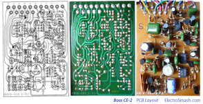
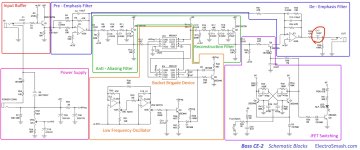
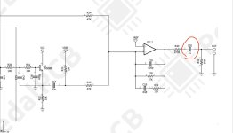
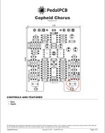
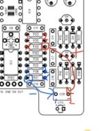
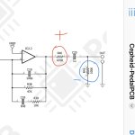
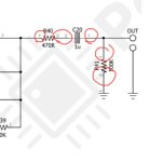
I’m preparing to build the Cepheid Chorus attempting to use parts as close to the original as possible. I’m mainly using the article on electrosmash.com as reference. One part has me stumped. What I’m finding in examining old pedals is there absence of box caps. The Cepheid calls for a 1uf box cap in C20. From what I think I can determine this was an Electrolytic in the original(C17 in the boss schematic). My questions are:
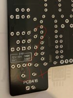
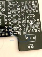
-If I wanted to use an Electrolytic how do I determine which direction the polarity is in the Cepheid PCB?
-Is there a general way to tell the direction for polarity on a PCB?

I’m an absolute beginner with an interest in recreating classic pedals. I am only just beginning to understand how to read schematics. The extent of my multimeter knowledge is how to test resistors, and test which direction diodes go. I’m still grappling with technical terms.
 

Attachments

  • IMG_3873.png
    IMG_3873.png
    675.9 KB · Views: 7
  • IMG_3880.jpeg
    IMG_3880.jpeg
    303.4 KB · Views: 7
  • IMG_3883.jpeg
    IMG_3883.jpeg
    82.8 KB · Views: 9
  • IMG_3881.jpeg
    IMG_3881.jpeg
    127 KB · Views: 7
Mainly, the best way is using a multimeter to find connectivity. If you find what C20 pad goes to what resisitor, you'll be able to determine which way to install the electrolytic. Sometimes you can see the traces visually, on this example the traces for C20 may be on the other side of the board.

On the Cepheid schematic, C20 is inbetween R40 and R41. If copying the electrolytic example, you can the see the positive+ goes to one side of R40, and the negative- goes to one side of R41. So I would take a multimeter and probe one pad of C20, and see which resistor it goes to. That'll tell you the polarity direction you need to put it in.

Another PCB image off of the Cepheid ordering page shows some connectivity visually of the surrounding components. I was able to more or less show what goes where. You just need to probe where each C20 pad goes, either R40 or R41. Compare this image to the schematic and you can kind of puzzle piece it together.

However, I have no idea of the tonal differences, if any, that would make. Anyone else can chime in on that.

Let me know if you need more help!

Cepheidedit.jpg
 
Last edited:
Ok. I tested for continuity. I got continuity from the right side pad only of R40(470k), to the right hand pad of C20. Continuity from the left pad only of R41(100k), to the left pad of C20. You can also see the traces from these points on the back and front of the board.

Just to clarify I understand. R40 is the positive side due to it coming before C20. And R41 is negative side because it comes after. Current is flowing towards C20 from R40 then onto R41. This dictates the positive side needs to be in the right pad of C20 and the negative in the left. Correct?
 

Attachments

  • IMG_3881.jpeg
    IMG_3881.jpeg
    35.5 KB · Views: 6
  • IMG_3886.jpeg
    IMG_3886.jpeg
    345.5 KB · Views: 4
  • IMG_3885.jpeg
    IMG_3885.jpeg
    754 KB · Views: 5
  • IMG_3883.jpeg
    IMG_3883.jpeg
    50.3 KB · Views: 6
I also just noticed these small numbers. Does “1” and “2” correspond with the left(1) and right(2) through holes for the components?
 

Attachments

  • IMG_3883.jpeg
    IMG_3883.jpeg
    23.1 KB · Views: 4
Yup looks good to me! You got it exactly right. The fact that you can physically see the traces confirms too. And it'll only be one pad of each resistor like you said, because that is the side to which it directly connects. Look at a couple connection points on the schematic, and try to find and probe the connectivity on the board. Do that a few times and it'll start to click how each component connects to the next. Like the other side of R41 (100k). The only place it connects to is ground. So if you probe those two spots, you'll get the beep, but nowhere else, since that's the only points of connection.

IMG_3881.jpeg
 
I'm not sure what those little numbers mean. I only pay attention to those if there's more than 2, like an IC chip or something which has 8 legs.
 
Back
Top