ADHD Wiring

Diatrive

Member
Hello all,

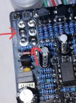
I have an ADHD populated and about to wire it. I don't understand the 1-7 on the bottom where the 4 holes usually reside. I use the breakout boards on the footswitch and don't know what to wire it to. Also the Out and In are at the top?! If the 1-7 does take the In/Out from the footswitch what happens at the top? Sorry, but I am completely confused as this is quite different than normal.
 
I just wired this one up, sounds very nice but I have a small issue with the bypass. it only passes signal in bypass with the bypass switch in the up position. With the switch down I get pink noise and no guitar signal. I rechecked the diagram and everything seems in order. I Haven't put it in an enclosure yet or wired in an LED but I don't see how that could be causing this.
 
Last edited:
Not being in an enclosure shouldn't be causing an issue as long as your jacks are grounded.

Can you post a pic?
 
Yep Here are a few pix.

I played it for an hour or so last night and noticed no anomalies. So I dont think I have any soldering issues to blame. The only thing I can think of is I used a different 3pdt than I usually use. But I believe I've used another from the same batch with your breakout board with no issues...
 

Attachments

  • 20190520_171726.jpg
    20190520_171726.jpg
    671.5 KB · Views: 53
  • 20190520_171759.jpg
    20190520_171759.jpg
    760.1 KB · Views: 51
  • 20190520_171805.jpg
    20190520_171805.jpg
    751.9 KB · Views: 50
  • 20190520_171838.jpg
    20190520_171838.jpg
    887.3 KB · Views: 48
its the DPDT that controls the bypass style
There are 2 solders on the DPDT that aren’t shiny like the rest in all the photos. Try resoldering the 2 joints I’ve marked. Those DPDT are nuts to take out if broken.

At least you know one of the bypasses is working at least, so that’s good.
 

Attachments

  • 053930E2-BC4F-4155-BC9F-C002FD0FE51E.jpeg
    053930E2-BC4F-4155-BC9F-C002FD0FE51E.jpeg
    500.7 KB · Views: 38
nope that's not it. :-/

I reflowed several areas, double checked the switch wiring, looked for small solder
bridges. nothing.

With the switch in buffered bypass mode, I tried touching different areas of the board, and wiggling components and switches... the only area that produced any change in signal (albeit just noise) were the pads of the leftmost 5457. I used the diode tester on my DMM and both 5457s read the same... so I assume they are working. what could it be?

How will I get to experience Mike Fuller's much touted "enhanced bypass"????
 
Last edited:
I replaced the DPDT switch... and resoldered my 3PDT switch. Now the pedal won't work at all. I replaced the op amp. No dice. Giving up on this one.
 
Sorry to hear of the problems. I'm curious if you managed to get it working again? I just built my first pedal (Uberdrive), but the ADHD was next on my list. I read your post with a little reluctance. Regardless, I received great advice in another thread to try an audio probe, which is a tool specifically designed to pinpoint problems. If you haven't already, might I suggest you try one?
 
Yes, the breakout board is included now.

ADHD-Panel.jpg
 
Depending on which version you have:


The new revision is the cleanest for sure. Prototypes are here and I'm waiting for DHL to bring components today.
I have the latest board - ADHD Overdrive
Any idea when the build doc will be released or is there a preliminary I can use?
Need the drill template and understand how to wire up with the additional pads and others for "EB"?!??
Just waiting this stuff so I can finish up building.
Thanks in advance.
 
I have the latest board - ADHD Overdrive

Wiring is straightforward. The Input / Output / DC jacks all connect directly to the pads at the top of the board.

If you're building true-bypass the six pads at the bottom center of the board are a direct connection to the standard 3PDT breakout board.

If you're building with the Improved Bypass module you'll directly connect all eight pads at the bottom to the Improved Bypass module.


I'll have a schematic posted shortly for cross referencing the various components / versions.

Schematic is here:
 
Last edited:
Back
Top