Aion Redshift Issue

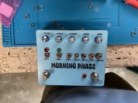
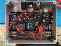
So for my second build, I chose the Aion Redshift. Lots of hard work and maybe a little above my skill level. Long story short, LEDs turn on. Bypass works. There is a signal when it’s turned on, but there is no “effect”. If I fiddle with the knobs enough, I can hear a little phase, but not much. It almost sounds like the effect is choked in the signal if that makes sense. Also, when I turn on the “vibrato” switch the signal cuts out completely. Any help would be appreciated. This pedal was a beast and I’m excited to get it to work. Also please ignore the shotty drilling. My first time…. IMG_1110.jpeg IMG_1108.jpeg
 
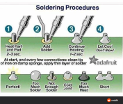
Be carefull with the toggleswitches when you will reflow them. They are really heat sensitive, the metal legs can get too hot and melt the plastic, it won't work correctly. Don't stay more than 2 or 3 seconds on the pads with your iron, and don't stay too long on the same toggleswitch.

8sn3zzvvccg71.png

If you reflow some pads on the soldering side, remember to take every heat-sensitive devices off the board : ICs, transistors. You didn't use sockets for your transistors, so be carefull around them, be quick and cautious.

Edit : You can post a picture of the soldering side if you are stuck, and voltage readings.

Check all suspicious pads with a multimeter in continuity mode, to see if there are some bridges, creating short circuits. If it rings, there is contact. Check the schematics in the instruction files to see if two components are supposed to be connected.
Clean the tiny spaces between pads, going quickly with the tip of the soldering iron, without overheating the pcb.

In continuity mode, you can also check if two components are connected as they should be, according to schematics.

Soon or later, on this build or the next big one, you'll need an audio-probe to follow the signal and see where it stops, to locate precisely where is the issue. There are lots of instructables online to build one, it's easy.


It's a good phaser with interesting mods, you won't be disappointed. Settings with Vibrato + low pass + 2 stages give some beautiful sounds.
 
Last edited:
Be carefull with the toggleswitches when you will reflow them. They are really heat sensitive, the metal legs can get too hot and melt the plastic, it won't work correctly. Don't stay more than 2 or 3 seconds on the pads with your iron, and don't stay too long on the same toggleswitch.

View attachment 58705

If you reflow some pads on the soldering side, remember to take every heat-sensitive devices off the board : ICs, transistors. You didn't use sockets for your transistors, so be carefull around them, be quick and cautious.

Edit : You can post a picture of the soldering side if you are stuck, and voltage readings.

Check all suspicious pads with a multimeter in continuity mode, to see if there are some bridges, creating short circuits. If it rings, there is contact. Check the schematics in the instruction files to see if two components are supposed to be connected.
Clean the tiny spaces between pads, going quickly with the tip of the soldering iron, without overheating the pcb.

In continuity mode, you can also check if two components are connected as they should be, according to schematics.

Soon or later, on this build or the next big one, you'll need an audio-probe to follow the signal and see where it stops, to locate precisely where is the issue. There are lots of instructables online to build one, it's easy.


It's a good phaser with interesting mods, you won't be disappointed. Settings with Vibrato + low pass + 2 stages give some beautiful sounds.
Awesome advice. Do I measure the voltage readings on the IC? Sorry I’m very new to this, but dedicated to learning the right way.
 
Advice when drilling (I've just spent my lunch time drilling 14 of the 20 holes needed for that specific build...) :
Print the template in the build doc, you can use the PCB to ensure it's printed at 100% scale and that everything lines up.
Later, you will also be able to apply the same trick with UV prints before ordering your enclosures.
When you are sure the scale is good, cut the template and use it to locate your holes, you can tape it to the enclosure
Use a punch to locate your holes, use support under the punch point to limit paint chipping. I use a spring loaded one with the red handle that I purchased on amazon for around 10$.
First, I like to drill tiny pilot holes using the punch mark as reference.
Then I use a step drill bit to bring those to the correct size.

When building with a lot of pots, switches, etc... place those in their correct location in the enclosure, then carefully align them with the board, with everything still inside the enclosure. You can screw the pots and switches to limit their movement, but leave room for some wiggle room.

Once the components are all inserted in the correct spot of the board, it's time to solder. You will be left with a populated board that you should be able to take in and out of your enclosure without too much trouble.
 
Update: went in and cleaned up my soldering. Started working. Also built an audio probe which is really a must have tool. Thanks for all of the advice.
I missed this thread earlier. Well done getting it up and running. I drill my enclosures by hand and really want to emphasize what @Nic and @KR Sound wrote above about drilling. Also - be careful. Bad injuries can happen fast, especially on bigger jobs with more holes. Easy to lose focus. Anyway, good job with a challenging build!
 
I've completed mine, here is some notes :

Level is the output volume of the effect, coming off of the MOSFET boost stage.

Vibrato mode cancels the clean signal, which results in a pitch vibrato effect. (Note that Depth should be set at 100% while in Vibrato mode since its only purpose is to attenuate the wet signal.)

Addition 1 :
Setting the volume trimmer
For such a large circuit, you may be surprised to find out that the only thing that needs to be set up during the build process is the volume trimmer. This controls the maximum boost level of the MOSFET output stage, which is essentially a Zvex SHO with tweaked values.

Set the volume control to full, then turn the trimmer up (clockwise) until the maximum available volume is to your liking. As with the SHO, expect a bit of crackle as the trimmer is adjusted.

I'll add here that in my experience (CCW = more output AND CW = less output)

Addition 2 :
R31 minimum volume resistor
The output volume control on the original Whetstone has a resistor that sets the volume level when the control is at minimum. Most people expect a volume control to go all the way down to zero, so it’s recommended to jumper the R31 resistor to make this happen. However, if you want it to be exactly like the original, use a 10k resistor here.
 
Last edited:
Back
Top