nate_noise
New member
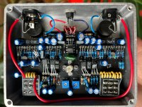
Hi Folks, I just boxed up the Electrovibe and am not getting any effect signal from it.
Bypass signal goes through fine, the lamp lights up and the gain/bias trimmers are working. I can hear a faint throbbing noise when the effect is engaged. I can effect the throbbing noise when I adjust the intensity and speed pots (speed footswitch seems to work too in that sense).
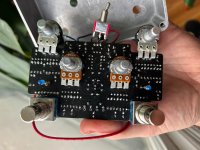
When I pulled it out of the enclosure to get the second photo, the wires to the chorus/vibrato switch came loose. (Would a weak connection on those result in no signal passing through?)
The very first time I plugged it in the lamp wasn't lighting up so I resoldered some of the weaker looking connections and the lamp started to work. My only concern now is that there might be a weak connection hiding underneath one of those double gang pots!
Any suggestions are welcome. Thanks!!
Bypass signal goes through fine, the lamp lights up and the gain/bias trimmers are working. I can hear a faint throbbing noise when the effect is engaged. I can effect the throbbing noise when I adjust the intensity and speed pots (speed footswitch seems to work too in that sense).
When I pulled it out of the enclosure to get the second photo, the wires to the chorus/vibrato switch came loose. (Would a weak connection on those result in no signal passing through?)
The very first time I plugged it in the lamp wasn't lighting up so I resoldered some of the weaker looking connections and the lamp started to work. My only concern now is that there might be a weak connection hiding underneath one of those double gang pots!
Any suggestions are welcome. Thanks!!