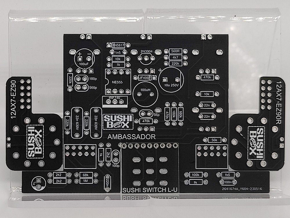
Ambassador - Matchless Hotbox project

Hey guys, i'm not sure if this is the place to put a question like this, but here i go... I've been watching threads about this and other pedal preamp layouts/pcbs and i just got stunned by this project. I've been dreaming with this idea of having a tube preamp in my pedalboard, i've recently acquired a Boss MS3 and i was wondering if this project could fit a relay switching capability of clean/drive channels to be triggered from the Boss, so i can make patches for it. It's the only thing that has me doubting about buying the Ambassador's PCB. Thanks in advance and wow,such lovely projects. TBH i dream to clone a Bogner Ecstassy blue channel (with tubes) in a pedal, not sure if its feasable but this could be my gain/high gain solution. Greetings!
 
Any way you could post a downloadable file in dwg, svg, etc. that can be imported for a dimensionally accurate drill template for the Ambassador and Particle Accelerator? I get a lot better results when I print the center points along with the graphics then drill afterwards. When I try importing PDF's they come in scalable so I can't get a proper "read" on actual size.
 
Building an Ambassador with some mods to conform more closely to a DC30 circuit. The DC30 coupling cap needs to be 560p/HV. The only thing I come across that small with the VDC rating are the silver micas as used in the Particle Accelerator tone stack. That fill the bill???
 
Building an Ambassador with some mods to conform more closely to a DC30 circuit. The DC30 coupling cap needs to be 560p/HV. The only thing I come across that small with the VDC rating are the silver micas as used in the Particle Accelerator tone stack. That fill the bill???
Yup, silver mica is what I use for those.
 
The DC30 schematic I have shows the first gain stage running thru both sides of a 12AX7 in parallel with a common cathode resistor of 1K5, but each triode having a different BP cap (25u & .1u respectively). In the Ambassador mod each triode will have its own cathode resistor so should I be looking a 3K on each?
DC30 Ch 1 schematic.jpg
 
The DC30 schematic I have shows the first gain stage running thru both sides of a 12AX7 in parallel with a common cathode resistor of 1K5, but each triode having a different BP cap (25u & .1u respectively). In the Ambassador mod each triode will have its own cathode resistor so should I be looking a 3K on each?
View attachment 54608
Nah, I would still run a 1k5 for the cathodes.
 
Would you still go with R21 in the Ambassador schem? It's not shown in the DC30. The DC30 does not show R24 either (10K Mid resistor), but in looking at Duncan TSC both ways I can't see how deleting R24 can be right. The AC30 schems also show the 10K so I'm figuring that hand scratched schem is in error.
 
The DC30 schematic I have shows the first gain stage running thru both sides of a 12AX7 in parallel with a common cathode resistor of 1K5, but each triode having a different BP cap (25u & .1u respectively). In the Ambassador mod each triode will have its own cathode resistor so should I be looking a 3K on each?
View attachment 54608
The cathodes of V1 are actually tied together. So both cathodes go to the1K5 resistor, the 25/25 and the .1µF caps. It's quite common for Matchless amps to do this. On the Hotbox I had the cathodes were done like this also. I'm not 100% certain why they do this but it's something you see in some higher end amps. Something to do with the 25µF setting the bass cut-off point and doing most of the filtering and the .1µF cap making sure the higher frequencies don't miss out - or something like that I was told. It's part of the black magic that makes Matchless sound good! You could probably get away without the .1µF cap altogether but I'd still use it just because.

I'm curious about the power supply. So this can run happily on 9V with a charge pump? What sort of amperage does the power supply need? I had a Hotbox, then a Dirtbox and finally a Badcat Two-tone. The Two-tone was the best sounding of all of them even though the circuit was virtually identical. I think the Two-tone may have been filtered a little more and had a bigger PT. If I could get some of that Two-tone OD sound from this I would be delighted!
 
FWIW, when I had a Hotbox or Dirtbox I ran them with bass and treble at around 9.00. I had gain around 9-10.00 too. Volume was just above unity. This way I had a balanced sound with plenty of bass, mids and treble. As you turn bass or treble up it scoops the mids. Most guys instinctively put bass and treble at noon - through my amps this doesn't really work so well. Turn them down for more mids.

It's interesting because the circuit is exactly a Vox top-boost channel. It's used in the Matchless Lightning as well. When I built a Lightning the EQ worked much as it does in an AC30. For some reason when used as a preamp/dirt pedal it behaves a little differently, possibly because it's going into a second tonestack in the amp. I have use these pedals through Fender SRRIs, '59 Bassman RIs, Marshall JTM45 RIs, home-brew Tweed Bassman, Deluxe, Twin (both lo-po and hi-po) and even a Bad Cat Hotcat. It worked beautifully with all of them. It also worked really well into the FX return in an older JCM2000 DSL50. I played a ton of gigs with these using the Super Reverb RI or the Bassman.

So I think I have to get me one or two of these PCBs!
 
"happily on 9v with a charge pump" is mostly correct -- meaning it runs with its own 9v power supply and gets high voltage/low amperage output from the inductor/555/mosfet design that keeps the preamp tube(s) running in spec. clarifying since most projects we build with charge pumps are self-contained and will run off of a daisy-chained power supply.
 
I'm curious about the power supply. So this can run happily on 9V with a charge pump? What sort of amperage does the power supply need? I had a Hotbox, then a Dirtbox and finally a Badcat Two-tone. The Two-tone was the best sounding of all of them even though the circuit was virtually identical. I think the Two-tone may have been filtered a little more and had a bigger PT. If I could get some of that Two-tone OD sound from this I would be delighted!
"Charge pump" typically refers to a switched-capacitor power supply like the IC7660, LT1054, etc. These are nice because they don't require big expensive external components, but they're limited as to the output they can provide.

The power supply I use in my pedals is a switched-mode power supply (SMPS) which switches a power MOSFET and utilizes a flyback inductor and high-speed rectifier to boost the output much higher, in this case around 250V. They're not amazingly efficient, but they're not terrible, with a measured efficiency of around 80%, meaning 1W of power in, 0.8W of power out, 0.2W lost to heat in the conversion. This means that the SMPS itself doesn't require tons of current since a 12AX7 will only pull a couple mA on the plate. The bulk of the current draw in these pedals is going to be on the tube filament (heater), which will pull a little under 300mA on a 9V supply. It will spike a little bit on power-on while the tubes try to pull as much current as they can to warm up, but a 9V supply of 800mA or so (I use a Cioks brick with a 9V 660mA tap and it works fine) is plenty. I typically recommend a OneSpot, which can provide up to 1700mA and easily run multiple tube pedals daisy chained.
 
Re: my mod to turn the Ambassador PCB into a DC30 preamp, one point of confusion. . . the traces through the tone stack area as shown in the build doc pics don't appear to agree with the actual traces from physical inspection. I've already soldered parts in place so I can't get a good visual in some areas, just what my meter is telling me. Can you verify the traces flowing out of the Treb pot & R18 thru the Bass pot and C10, C14 and into R24?

Ambassador TS excerpt.png
Per the Build Docs: BLUE are "top" traces, PINK are "bottom" traces based on my transcription of the pcb pics in the build docs.

Here's what I'm finding. R24 goes nowhere, grd on both ends? Why isn't the P3 Treb pot & right side of C10 not connecting to P1 of the Bass pot?

sketch.jpg
 
Last edited:
Re: my mod to turn the Ambassador PCB into a DC30 preamp, one point of confusion. . . the traces through the tone stack area as shown in the build doc pics don't appear to agree with the actual traces from physical inspection. I've already soldered parts in place so I can't get a good visual in some areas, just what my meter is telling me. Can you verify the traces flowing out of the Treb pot & R18 thru the Bass pot and C10, C14 and into R24?

View attachment 55760
BLUE are "top" traces, PINK are "bottom" traces based on my transcription of the pcb pics in the build docs.
You'll have to remind me, do you have one of the original PCBs with the backwards bass pot? Or is it a v1.0 from June 2023? The v1.0 also says "BBB FIX" on the bottom right side.

This is the v1.0 version layout, bright red is top layer, blue is bottom layer, darker red is internal split power plane.

Screenshot 2023-09-03 222102.jpg
 
The code on my board is "2641674A_Y623-230620". . . Jun'23? Anywho, what you posted above is what I've got. Also confirm, the GRD leg on R24 is reversed as well, the "left" eyelet now runs to GRD and the "right" eyelet ties to C14? Also, I show Bass pot P1 as running to GRD. . . WRONG. . . it's P3 running to GRD. Thx!!
 
The code on my board is "2641674A_Y623-230620". . . Jun'23? Anywho, what you posted above is what I've got. Also confirm, the GRD leg on R24 is reversed as well, the "left" eyelet now runs to GRD and the "right" eyelet ties to C14? Also, I show Bass pot P1 as running to GRD. . . WRONG. . . it's P3 running to GRD. Thx!!
Screenshot 2023-09-04 105539.jpg

Zoomed out a little for you, hope it helps.
 
Bumping the thread to let everyone know that Ambassador PCBs are no longer be available from Sushi Box, from now on they will be sold by Conspiracy to Commit Electronics (@C2C Electronics). I'm still involved, but trying to be less in charge.


Enclosures are still available, but listed separately.

 
I'm working off this as the proposed mod of the Ambassador to give me a DC30 preamp. Any comments would be appreciated. Disregard any references to the foot switch, etc. I'm strictly focused on the signal path at this point.

Ambassdor schem (DC30 mod).jpg DC30 schematic.jpg
 
Back
Top