SOLVED Any Amp Experts??? Mojotone 5F2A Issues...

Fingolfen

Well-known member
Any amp experts... I've gone back through this circuit about 4 times and still can't figure out what's wrong.

I've been trying to finish up this Mojotone 5F2-A... Passed the dim bulb testing, etc. but when I put in the tubes I get a high pitched squeal that scales with the volume knob, and any tones are harsh, robotic, and clearly into breakup. Definitely isn't sounding like it should... to say the least...

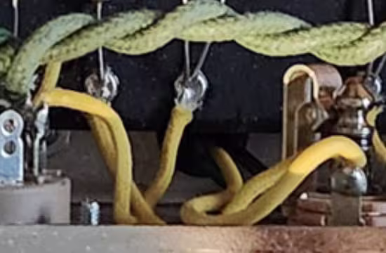
As currently built (I've taken the tubes and speaker back out)

5F2A In Progress.jpg

Wiring diagram (for 4 Ohm speaker - which is what I have)

Tweed Princeton 5F2A wiring diagram.jpg

Schematic (note, the schematic shows the green 8 ohm lead from the output transformer wired, but per the diagram above and the impedance of my speaker I'm using the yellow)

Tweed Princeton 5F2A Schematic.gif

Thoughts??? Help???
 
Last edited:
I haven't built an amp, but I read that one key step before putting tubes in is to check voltages at all the important points. You might need the rectifier tube in to do that. If all the tube sockets are getting correct voltages then the problem is probably on the signal path, and in your case probably is as the noise scales with volume. I guess the process there is to turn power off, drain the caps, then start at the jack socket and check that the connections at every node as you go downstream to the speaker are what they should be, and that there are no bad solder joints on the components.

You know this, but be careful debugging as there will 350V DC or thereabouts at some points when it's powered up and that is enough to kill you
 
Hey, that's a great looking build.

Those 5W cathode resisters get HOT and will fry capacitors that touch them. It would be prudent to have at least a Popsicle stick thickness in between it and the capacitor! I usually leave as much room as I can, but there's not a lot of room to play with on a champ...
 
It's there, it was just hiding...

5F2A In Progress 2.jpg

That being said, I've been digging around and I can't seem to find a path that I can actually isolate and measure this 22K resistor (I only see the 1.5K which actually measures 1.39K):

Tweed Princeton 5F2A wiring diagram.jpg

Going back to the schematic, it looks like there is some tortuous path involving ground where I would only measure that 1.5K, but it seems odd...


Tweed Princeton 5F2A Schematic 2.gif
 
It's there, it was just hiding...

View attachment 69361

That being said, I've been digging around and I can't seem to find a path that I can actually isolate and measure this 22K resistor (I only see the 1.5K which actually measures 1.39K):

View attachment 69362

Going back to the schematic, it looks like there is some tortuous path involving ground where I would only measure that 1.5K, but it seems odd...


View attachment 69363
This is the NFB circuit. The 22k is the NFB resistor, I forget what the 1.5k is called.

This from Rob Robinette's site about positive feedback, which I have never personally witnessed but have seen online more than a few times

"Since this amp uses negative feedback (NFB) there is a 50-50 chance you will get a very loud positive feedback squeal when you first power up the amp. If this happens simply shut down the amp, verify the filter caps have zero voltage (they should since resistor R14 will bleed the caps) and swap the output transformer blue and brown primary wires (swap both sets)."

I am brain dead today due to going to bed at 2:20am and Izzy (23 year old cat) screaming his head off at 5:30am to go outside. The "I'm going to effing die if I can't watch the sunrise" scream. I never really went back to full sleep after that.

Perhaps if you search his site you may find a reference of what to do if you have positive feedback instead of negative feedback with a single ended class A amp.


This has the what to do if it makes weird sounds thing, which can include microphonic tubes


I need a nap....... ZZZzzzz
 
Hey, that's a great looking build.

Those 5W cathode resisters get HOT and will fry capacitors that touch them. It would be prudent to have at least a Popsicle stick thickness in between it and the capacitor! I usually leave as much room as I can, but there's not a lot of room to play with on a champ...
That’s where my mind went at first as well. Never heard of it on a SE amp.
But the fix is usually flipping the primary leads
Another thing he could that would be quicker is snip the NFB wire, no feedback no oscillation.
I’ve heard it only a few times on PP amps, and it’s more often a low howl than a high frequency thing.
Other than that my bets would be lead dress, and for that I’d need to see pics of his actual build.
There's a couple above, and I can get you more pictures if needed. I've run continuity test and the connections appear to be clean... but I'm going to go through them again...
 
Extra eyes are always awesome... unless they're growing out of your head...

So in addition to the photos above, here's some more detail photos. Let me know if you want anything else... pixels are cheap!

5F2A Detail - 01.jpg

5F2A Detail - 02.jpg

5F2A Detail - 03.jpg

5F2A Detail - 04.jpg
 
Extra eyes are always awesome... unless they're growing out of your head...

So in addition to the photos above, here's some more detail photos. Let me know if you want anything else... pixels are cheap!

View attachment 69383

View attachment 69384

View attachment 69385

View attachment 69386
Nothing jumps out at me. Wiring looks right, no cold joints. The only things I can’t tell are if the center lug and the lug with the 500pf cap are touching. Also can’t see any under board wiring.
Assuming that’s good, the things I’d check for- does the oscillation change with knob position? Does it change when you move wires around (use a chopstick!)?
In other words- lead dress.
Next tap tubes- could be microphonic tube or even microphonic capacitor. Again. Chopstick taps.
Second question is around the NFB coming off the 4ohm tap and not 8. Shouldn’t matter
Finally lift one end of the NFB resistor to eliminate if it’s a phasing issue with the transformer. Never heard of it on single ended but I learn every day.
 
It's a long shot, but the cathode wire and output wire are touching, which could mean a bit of capacitive coupling.

temp-Image9t-Px4-U.avif
 
As I was cooking my steak and potatoes (delicious btw, but that's a different thread) I thought about the NFB. The resistor value is calculated for a specific output ohms. So you have to use a different resistor if you're using 4 ohm for the secondary instead of 8 ohm.

I looked up the original schematic and there's nothing, then I did find it at the Fender history of the champ page, it's supposed to be four ohm and you're using the four ohm.

Crap, so that's not it.... But as was mentioned, you can disconnect the NFB wire from the output jack for "raw" mode and see if it gets rid of the extreme noise. If it doesn't at least we've eliminated the NFB and start looking at maybe tracing the signal to see where it gets crazy.

But, hey, there's this cool link I found:

 
It's a long shot, but the cathode wire and output wire are touching, which could mean a bit of capacitive coupling.

temp-Image9t-Px4-U.avif
And those wires are running parallel, all wires are supposed to intersect as close to a 180 degree angle as possible, which is why you see curly-que wire dressing on old fenders. High voltage will just induct into the next wire if they are close and parallel.....
 
So have you tried swapping the red & blue OT wires yet? I don't see a comment that you ruled this out, sorry if I missed it. I finished off a build of this someone had started, and this ended up being the issue. I contacted mojotone since there seemed to be some discrepency on which wire goes where from there schematics to others I found. The answer was essentially, "guess and check"! If you get tons of feedback, swap em. This lines up with the "50/50" comment above.
 
Nothing jumps out at me. Wiring looks right, no cold joints. The only things I can’t tell are if the center lug and the lug with the 500pf cap are touching. Also can’t see any under board wiring.
Assuming that’s good, the things I’d check for- does the oscillation change with knob position? Does it change when you move wires around (use a chopstick!)?
In other words- lead dress.
Next tap tubes- could be microphonic tube or even microphonic capacitor. Again. Chopstick taps.
Second question is around the NFB coming off the 4ohm tap and not 8. Shouldn’t matter
Finally lift one end of the NFB resistor to eliminate if it’s a phasing issue with the transformer. Never heard of it on single ended but I learn every day.
I couldn't tell if they were touching either. I usually take insulation off of another wire and slip it over the legs on those pot to pot caps and resistors.... Then I got tired of wasting wire so I bought some empty PTFE insulation, was kinda surprised they actually make such a thing.
 
I couldn't tell if they were touching either. I usually take insulation off of another wire and slip it over the legs on those pot to pot caps and resistors.... Then I got tired of wasting wire so I bought some empty PTFE insulation, was kinda surprised they actually make such a thing.
I need to find some of that! We always called it “spaghetti tubing”, but both with amps and pedals, I always seem to need to insulate a lead or 3 here or there
 
Back
Top