Anyone want to take a stab at drawing up the off board wiring for this fuzz face?

Cjs1960

New member
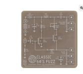
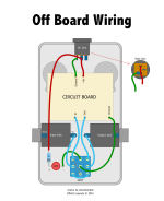
Anyone want to take a stab at drawing up the off board wiring for this fuzz face? I was given the attached off board diagram but I don't see where I would put the ground wire on the bottom of the board in the wiring diagram as there isn't one on the pcb. I also want to run it battery only with no LED. Is it as simple as using the battery wires in place of the DC jack shown, red for plus, black for neg? and do I just omit the red wire going to the resistor and then led/switch?
 

Attachments

  • Screen Shot 2022-09-03 at 2.00.41 AM.png
    Screen Shot 2022-09-03 at 2.00.41 AM.png
    717.1 KB · Views: 33
  • image.png
    image.png
    229.4 KB · Views: 34
Anyone want to take a stab at drawing up the off board wiring for this fuzz face?
Sorry, not today.

I was given the attached off board diagram but I don't see where I would put the ground wire on the bottom of the board in the wiring diagram as there isn't one on the pcb.
The green ground wire from lug 5 of the 3PDT to the board is solely there for the LED to function...

I also want to run it battery only with no LED.
Uhm, why?
LED tells you if it's on or off — a proven useful feature;
Goes without saying, but I'll say it anyway: Battery-only is wasteful, but understandably isolated amongst other reasons to go battery-only. It's your pedal, do with it what you will.

Is it as simple as using the battery wires in place of the DC jack shown, red for plus, black for neg?
Yes.

and do I just omit the red wire going to the resistor and then led/switch?
For No LED:
Omit the red wire going to the resistor,
Omit the resistor
Omit the LED
Omit the green wire from the LED to the switch
Omit the green wire from the switch to the board.
Omit the 3PDT and use a DPDT, since you're not using an LED on/off indicator.
 
Oh yes there is a ground connection on the board! You only need one. As long as all of the ground points connect to ground you're good. So join the ground from the board to the ground on a jack, or the power connector.

I would show you where on the pic but my photoshop doesn't work on this computer.
 
Ground all your jacks to this point, I'd personally pick a jack and then wire all the grounds and battery negative to that jack (even better use a stereo jack so the battery doesn't drain when not in use) , then run an additional wire to this board. To use a stereo jack for the battery, hook the battery negative to the ring of the stereo jack, so when you insert a mono plug, the plug will complete the connection and put your battery to work.


1662205791576.png
 
I had more time tonight, I believe this is what you wanted:
- Battery snap only
- No LED (means you can use a DPDT stomper or toggle, or just use 2 poles of a 3PDT if you don't have a DPDT)


SCHEMATIC FUZZ ELS diagram by Feral Feline.png


... and don't forget to unplug the pedal when not using it or you'll come back to a dead battery

PS: (Just now realised I didn't show the switching jack to disconnect the battery when nothings pluggged in, but I've run out of time...).
 
I had more time tonight, I believe this is what you wanted:
- Battery snap only
- No LED (means you can use a DPDT stomper or toggle, or just use 2 poles of a 3PDT if you don't have a DPDT)


View attachment 31699


... and don't forget to unplug the pedal when not using it or you'll come back to a dead battery

PS: (Just now realised I didn't show the switching jack to disconnect the battery when nothings pluggged in, but I've run out of time...).
It should be a stereo jack, not necessarily a switching jack. The battery lead goes on the third lug.
 
Back
Top Bottom