Hi everyone and many thanx who can help me.
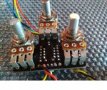
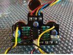
I've recently bought a AwfulWaffle Kit and after receiving the package, I started assembling it and after 2 hours the PCB was complete with all its components.
I proceed to the "smoke test" - ok
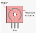
I proceed to the sound test - fail, pressing the foot switch turns on the led but the pedal is in bypass, pressing the foot switch again overoveroveroversaturated sound! The potentiometers do not control anything and have a strange behavior, they seem almost like variable capacitors.
I remove the power supply and carry out a visual inspection:
resistance values and position - ok
capacitor values and position - ok
IC orientation - ok
input and output - ok
bad welds or problems of any kind - nothing to report ..
but then what is it?
Having assembled everything without posing too many problems with what I was doing, I take the wiring diagram and the layout and I look at it ... and here the first doubts arise.
My attention falls on the switch ...
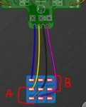
The switch comes with 4 wires: P1 P2 GND SW


In position A:
SW goes ground with GND (LED lights up)
P1 goes to ground with GND
In position B:
P1 and P2 close (distortion described above)
Looking at the scheme the two positions act as follows.

In the empirical tests, I also tried to close P2 to ground together with SW, in this way, the LED lights up and a distortion comes, always very pushed but very muffled ... even here pot have strange behavior.
If P1, P2, SW and GND are open, the pedal is disengaged correctly.
Thank in advance for the support.
Marco.
I've recently bought a AwfulWaffle Kit and after receiving the package, I started assembling it and after 2 hours the PCB was complete with all its components.
I proceed to the "smoke test" - ok
I proceed to the sound test - fail, pressing the foot switch turns on the led but the pedal is in bypass, pressing the foot switch again overoveroveroversaturated sound! The potentiometers do not control anything and have a strange behavior, they seem almost like variable capacitors.
I remove the power supply and carry out a visual inspection:
resistance values and position - ok
capacitor values and position - ok
IC orientation - ok
input and output - ok
bad welds or problems of any kind - nothing to report ..
but then what is it?
Having assembled everything without posing too many problems with what I was doing, I take the wiring diagram and the layout and I look at it ... and here the first doubts arise.
My attention falls on the switch ...
The switch comes with 4 wires: P1 P2 GND SW


In position A:
SW goes ground with GND (LED lights up)
P1 goes to ground with GND
In position B:
P1 and P2 close (distortion described above)
Looking at the scheme the two positions act as follows.

In the empirical tests, I also tried to close P2 to ground together with SW, in this way, the LED lights up and a distortion comes, always very pushed but very muffled ... even here pot have strange behavior.
If P1, P2, SW and GND are open, the pedal is disengaged correctly.
Thank in advance for the support.
Marco.


