Basic Workflow Tips for Building a PedalPCB

Jovi Bon Kenobi

Well-known member
Hello! This is my method for building a PedalPCB from start to finish. Is it the right way? Not necessarily. It's just what works for me and I hope it sheds some light on certain steps in the process along the way. I created this as a reference guide for anyone to use if needed. Thanks for reading!

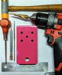
Step 1: Drill the enclosure.
I recommend having this done before starting any soldering as it makes test fitting the fully populated board a whole lot easier later.
fig. 1
IMG_20190910_103740.jpg

*Key step* Always print the drill template at 100%. Some printers default to "fit to page". You don't want "fit to page" because the template will be about 5% smaller if you do so...enough for a future struggle.

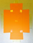
To attach the template to the enclosure I like using double sided tape. Place the template printed-side down on a flat surface. Put tape on the inside four corners of the drill template face and one in the middle.
fig. 2
IMG_20190910_093035.jpg


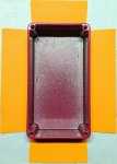
With the template tape-side-up on a flat surface I then carefully lower the enclosure down onto it.
fig. 3
IMG_20190910_093707.jpg

Once it's on centered and true fold the four sides of the template flush to the enclosure and secure them with regular tape. Use a center punch or an awl and hammer to mark the holes. I use a step bit and cordless drill to make the holes though a drill press is best. I always start by drilling a little bit where I marked the center to give me a more secure starting point then move to the next until all are done this way. This allows me to eyeball and see if I need to correct my final pass for each hole.
*Side note* After marking the enclosure, some of us like to use a regular drill bit to drill a pilot hole before moving onto the step bit.
fig. 4
IMG_20190910_100834.jpg

Drill all holes then clean up any burrs from drilling with a needle file, if needed. Thoroughly clean inside and out afterwards with a towel and isopropyl alcohol. Optional, compressed air is nice to have to blow out any remaining debris.
fig. 5
IMG_20190910_102437.jpg
 
Last edited:
Step 2: Prep
Clean your PCB. I use isopropyl alcohol and a paper towel.
fig. 6
IMG_20190909_105453.jpg

Step 3: Audit components & populate the board
With your digital multimeter measure all components for proper value before adding them to the board.
fig. 7
IMG_20190910_112454.jpg

A flux pen is recommended. It will help you avoid any future potentially fouled solder joints. Turn the board over and flux the pads which you will be soldering. Do this in small areas at a time so you don't get flux all over yourself.
fig. 8
IMG_20190909_105720.jpg

Clean your leads
Again, isopropyl alcohol and towel here.
fig. 9
IMG_20190909_110108.jpg
Or...
When I clean the leads, I'm usually using scotch-brite to remove the tarnish on my NOS parts
Flux your leads...the area that will touch the PCB pads when properly seated. Start at the component and go out about 1/8".
fig. 10
IMG_20190909_110259-01.jpeg

Bend the leads. I like to hold the resistors down and bend the leads away from each other a bit so they stay in place when turning the board over.
fig. 11
IMG_20190909_110543.jpg

Another option is to use blu-tack or poster putty. When using this, try to not smash it down too close to the resistors or it will touch the exposed leads and melt when soldering. I find this method particularly useful when populating box film caps and sockets so they go on straight and tidy.
Solder time
Most people have preferred temps, tips, and solder, but for the sake of this guide, what I used is a fine point chisel tip in an iron set to roughly 700°F (370°C) and Kester .80mm 63/37 "no-clean" solder. This is not a definitive guide, rather just my current preference.

Low profile components go in first, i.e. resistors, diodes, next are sockets, trimpots, then film capacitors and electrolytics. Clip the leads after soldering each component or area of components.
fig. 12
IMG_20190909_111615.jpg
fig. 13
IMG_20190910_120722.jpg

...continued below
 
Last edited:
Step 4: Cleaning the PCB and adding potentiometers and switches
The board is populated. In this photo you see that I haven't added the transistors into their sockets yet. They get in the way when soldering the pots and switches so I'll add them later. The same applies for any socketed component, i.e. IC's
fig. 14
IMG_20190910_220302.jpg
*Yes, it missing a capacitor. It's optional on this PCB.

But look how dirty it is underneath.
fig. 15
IMG_20190910_221418.jpg

Cleaning the PCB
The method I use to clean all the flux residue from the bottom is simple. Isopropyl alcohol, a toothbrush, and paper towel. *Kim Wipes are preferred over paper towel as they don't produce lint*
fig. 16
IMG_20190910_221828.jpg

Lay the towel over the bottom side of the PCB and hold it in place. Saturate the paper towel in isopropyl alcohol and brush for a few seconds. When the towel starts to break down or look "fluxy" move to a dry patch of towel and repeat. Do this three or more times depending on how dirty it was. This towel method keeps the alcohol and residue from running through to the business side of the board. Here it is all clean.
fig. 17
IMG_20190910_222337.jpg

Time to add the potentiometers
First, bend the the legs into a "\ | /". Doing this gives the potentiometer legs some outward tension when you insert it into the pads on the PCB so it won't fall out. Next, bend your potentiometer legs to about an 80° acute angle. This gives you clearance from the other pot solder pads and the offboard wiring we will do later. Like this...
fig. 18
20190914_153703-COLLAGE-01.jpeg

Add flux to the PCB pads and potentiometer legs and insert them into the board. They should stay in the board without falling out. Do not solder them now. Notice how the pots are pushed flush against the board? We don't want this, especially if there is no plastic cap on the pot. Read on to see the couple additional steps we will take before soldering them in.
fig. 19
IMG_20190911_095417.jpg

Test Fitting
Drop the board (now with unsoldered pots) into your enclosure. I do this on the outside so I have easy access when soldering. My drill holes are symmetrical so this works. If your holes aren't symmetrical (due to drilling misfires or asymmetrical toggle layout) drop it into the the inside of the enclosure. I then gently hand-tighten the potentiometer nuts until they are just snug. This just temporarily holds everything secure while we get ready to solder.
fig. 20
20190911_101246-COLLAGE.jpg

What if you have toggle switches?
If you have toggle switches flux pen the lugs and it's corresponding pads then gently hand tighten them into the enclosure before dropping your board (with unsoldered pots attached) into the holes. Basically, with this technique, everything is anchored to something so that you have a solid base to work from. Like this...
fig. 21
IMG_20190909_095238.jpg

Avoiding potential grounding issues
To avoid any possibility of creating a short I lift the PCB up slightly to create a gap between it and the pots. The tension created by previously bending the pot legs holds the PCB secure. Also, in this photo below I insulated the dual gang pot that doesn't have a dust cover with pickup coil tape for added insurance.
fig. 22
IMG_20190911_102348-01~2.jpeg

Solder the potentiometers and switches
Do a final once over to align and center the board, pots, and switches if needed. There is a bit of wiggle room. I like to solder one leg then move to the next potentiometer or switch, reducing the chance of overheating. Repeat until all legs and switch lugs are done. Unscrew the nuts holding the potentiometers down and remove your completed PCB. When the time comes, it will now drop into your enclosure holes with no resistance.
fig. 23
IMG_20190911_121343.jpg

Continued below...
 
Last edited:
Step 5: Offboard Wiring
fig. 24
IMG_20190911_125623.jpg
For a standard 125B build using all the components seen in fig. 24 I cut all my offboard wires to the same lengths:

Footswitch breakout board to jack "tip" lug's = 5"
Footswitch breakout board to main board = depends on main board size
DC jack to +/- on the board = 1 ⅞"
Board grounds to jack "sleeve" lug's = 2 ¼"

Clean the breakout board (if using), flux board and switch lugs, and solder it to the footswitch.

Flux the wires and the pads they go into then drop the wires into the pads. Lay a piece of tape across all wires and then around the footswitch to hold them in place then solder em in. Like this...
fig. 25
IMG_20190914_133311.jpg

Clip the leads then clean off the flux residue from the breakout board.
Bend the middle four leads coming from the breakout board into a "u", flux them and the pads on the board, then insert them into the board, solder, and clip excess.
fig. 26
IMG_20190914_134602.jpg

Repeat the process for the north end of the board. Notice I pre-clipped the leads that go into the DC power jack lugs so that I don't have to after soldering them in place.
fig. 27
IMG_20190914_132647.jpg

Add heat-shrink to the input/output jack wires (if using), solder on the jacks, then position and shrink your tubing.
fig. 28
IMG_20190914_135815.jpg

Final assembly.
Install your DC jack into the enclosure and position it so that the longer lug is on the left and the shorter lug is on the right. Tighten it down then flux it's lugs.
If using an LED bezel install it now. For the one I use in the photo below I like to slightly flare out the opening after fitting it in the enclosure. I do this by gently bending the tabs a bit. This allows the LED to drop right in.
fig. 29
IMG_20190914_164623.jpg

Test your LED so you know it works. Flux the LED legs and the pads on the board where it will go and insert it into the board.
Drop your completed board into the enclosure and hand tighten all of the nuts and washers onto the pots and switches.
Solder the DC wires to the power jack. You will need to finesse the input/output jacks out of the way so you have easy access while doing this.
Solder the LED and then clip the leads.
Tighten down your input and output jacks.
Install any of the socketed the components into their sockets if you haven't already, i.e. transistors, IC's, diodes, etc...
fig. 30
IMG_20190914_165934.jpg

Do a once over on all your nuts to make sure everything is secure. All done!
fig. 31
IMG_20190914_171513.jpg

Rock out!
 
Last edited:
When I clean the leads, I'm usually using scotch-brite to remove the tarnish on my NOS parts. After soldering, I usually flood the board with IPA and scrub with a toothbrush. I do this before installing pots and trimpots so I don't transport flux into the pot. Don't tell my wife I use her toothbrush. :p
 
OK! I think this is done. It took me a few days as I was quite busy with real life work and such. Please let me know if you think anything seems amiss. I added "fig." titles to each photo so if anyone needs to reference or link it they can pinpoint exactly where to scroll to.
 
Excellent Tutorial and tips !

I’ve been fighting myself on the wiring but now I see how you get that nice clean wiring look ...sweet

Also I’ve been wondering how to do fig.21 on my next build..got it now !

Thanks for taking the time for the step by step tutorial...

Mike
 
Step 5: Offboard Wiring
fig. 24
View attachment 1388
I cut all my offboard wires to the same lengths:
Step 5: Offboard Wiring
fig. 24
View attachment 1388
I cut all my offboard wires to the same lengths:

Footswitch breakout board to jack "tip" lug's = 5"
Footswitch breakout board to main board = depends on board
DC jack to +/- on the board = 1 ⅞"
Board grounds to jack "sleeve" lug's = 2 ¼"

Clean the breakout board (if using), flux board and switch lugs, and solder it to the footswitch.

Flux the wires and the pads they go into then drop the wires into the pads. Lay a piece of tape across all wires and then around the footswitch to hold them in place then solder em in. Like this...
fig. 25
View attachment 1414

Clip the leads then clean off the flux residue from the breakout board.
Bend the middle four leads coming from the breakout board into a "u", flux them and the pads on the board, then insert them into the board, solder, and clip excess.
fig. 26
View attachment 1416

Repeat the process for the north end of the board. Notice I pre-clipped the leads that go into the DC power jack lugs so that I don't have to after soldering them in place.
fig. 27
View attachment 1415

Add heat-shrink to the input/output jack wires (if using), solder on the jacks, then position and shrink your tubing.
fig. 28
View attachment 1417

Final assembly.
Install your DC jack into the enclosure and position it so that the longer lug is on the left and the shorter lug is on the right. Tighten it down then flux it's lugs.
If using an LED bezel install it now. For the one I use in the photo below I like to slightly flare out the opening after fitting it in the enclosure. I do this by gently bending the tabs a bit. This allows the LED to drop right in.
fig. 29
View attachment 1421

Test your LED so you know it works. Flux the LED legs and the pads on the board where it will go and insert it into the board.
Drop your completed board into the enclosure and hand tighten all of the nuts and washers onto the pots and switches.
Solder the DC wires to the power jack. You will need to finesse the input/output jacks out of the way so you have easy access while doing this.
Solder the LED and then clip the leads.
Tighten down your input and output jacks.
Install any of the socketed the components into their sockets if you haven't already, i.e. transistors, IC's, diodes, etc...
fig. 30
View attachment 1422

Do a once over on all your nuts to make sure everything is secure. All done!
fig. 31
View attachment 1423

Rock out!
Sweet tutorial. I’ve already figured out most of the process but I wish I would have had this on my first couple of pedals. Very thorough. One question though is how do you get your PCB so shiny clean and black? I flush my board with 99.9% isopropyl. It’s clean but not that clean.
 
Sweet tutorial. I’ve already figured out most of the process but I wish I would have had this on my first couple of pedals. Very thorough. One question though is how do you get your PCB so shiny clean and black? I flush my board with 99.9% isopropyl. It’s clean but not that clean.
You know, I'm not sure. It may just be the lighting. The last photo was the only one taken outside...in diffused light of a shaded area. I only thoroughly clean the bottom side of the PCB after all small parts go in. There is minimal flux on the business side because I never flux the pads on that side...so I usually leave that alone.
 
WOW! Impressive. You put a lot of time and effort into putting this together. If everyone built their pedals this well, I'll wager we'd have a lot fewer posts in the Troubleshooting forum.
Thanks Chuck! That was my original aim. :D I am not that skilled at debugging or offering electronics knowledge, so I figured I'd go the other route and go full detail on what I do know.
 
Outstanding pro-tips. Appreciate the notes on flux cleaning in particular... need to try this method next time. Also the heat shrink is a sign of pro quality equipment for sure. :) Thanks a ton!
 
What a great tutorial. Thanks for taking the obvious time to put this together. I've been doing this for longer than I care to admit and I picked up a few cool pointers here.

Side note to testing parts: Tayda and eBay have cheap but cool parts testers that sometimes aren't as accurate as as a good DMM but are quick and easy parts testers for resistors and caps especially. I know they've been talked about here before but REALLY reduce the chance of mixing up values like 4k7/47K. Those can be a bugger if you're looking for wrong parts while troubleshooting, especially if you have a mix of 4 and 5 band color codes. You can be looking right at the part and totally miss the value. It's a minimal investment for your bench and takes only a few seconds to verify parts as you stuff them. It's amazing how low your wrong-parts-in-a-build numbers drop to.
 
Very nice tutorial, may I suggest @PedalPCB to pin this post so beginners see it? As long as it's not full of misinformation... ;)

I'm surprised by something:
It looks like you do the full enclosure before testing the pedal at all. Is it so? As a newbie I need a small victory first by testing the thing like this: Squid-circuit.png

Maybe I'm just an insecure brat...
 
It looks like you do the full enclosure before testing the pedal at all. Is it so?
I know I'm playing with fire and may eventually be burned, but since building pedals in this very meticulous and deliberate way I have not run into any troubleshooting issues. The last 20 or so PCBs have worked perfectly. I would always suggest testing it first before going into the enclosure.
 
Back
Top