SOLVED Blue Breaker no sound

Kyle004

Member
Hey guys,

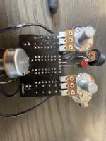
New here, first pedal build and trouble shoot. I am building a blue breaker and by pass works great but when I switch it on i get no output. i made an audio sniffer and i get sound into pin 3 (and none oft he other pins) of the tl072 but no sound coming out. i swapped op amps that i had extra and all 3 same issue. Im unsure about how the ic actually work would the next step be to check negative voltage on pin 2 and or make sure there is good continuity to pcb ground on pin 4? any help would be appreciated. looking forward to being part of the community!
 
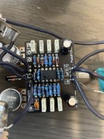
FF4C2ED1-94F1-46E3-804E-C23CD2E75F63.jpeg
Update of where its at after retouching and cleaning again. I also changed out the ic holder i had i was worried about some stray solder underneath of it possibly but no change.

edit I swapped out power jacks now i have 9v in and 9v at led. 0v at d5 is my board bad?
 

Attachments

  • 0CB074BA-2F9A-4D3E-83CA-99A321A11B1E.jpeg
    0CB074BA-2F9A-4D3E-83CA-99A321A11B1E.jpeg
    1.2 MB · Views: 20
Last edited:
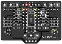
Yes D5 is where your power goes in, so you should have whatever your adaptor puts out 9v ish at the anode + side then 9v, less the 0.4v ish diode voltage drop at the cathode - side so 8.6v

Make sure you get good contact with your meter probes, I always take voltage readings 2 or 3 times just to make sure I'm getting a good connection
 
Last edited:
Yes D5 is where your power goes in, so you should have whatever your adaptor puts in 9v ish at the anode + side then 9v less diode voltage drop at the cathode - side so 8.6v ish
Ok im gonna try to jumper to get power to that diode. Im assuming the hole at d5 is still fine its just the path in the board that is broke i think
 
Ok im gonna try to jumper to get power to that diode. Im assuming the hole at d5 is still fine its just the path in the board that is broke i think
Try reflowing again first

As you say you can jumper it if necessary it's for polarity protection

Although unlikely diodes can be damaged with excessive heat from soldering
 
Try reflowing again first

As you say you can jumper it if necessary it's for polarity protection

Although unlikely diodes can be damaged with excessive heat from soldering
By reflowing you just mean heating it up again and putting a little more solder on?

Ill do a diode test on it. Im getting 0v to both sides of it. My thought was jumper the + pad to the left side of d5 but yes i will reflow and do the continuity check before i do that for sure
 
Do the continuity test outlined by @music6000 first, place your leads on the component legs rather than the solder pads where you can

You don't need to add more solder just re melt the solder already there hold your iron on it for 4 seconds until you see a nice flow connecting the diode legs to the solder pad
 
what is the "OL" reading on the D5 annode? Is your meter set to read volts? you want to test the components when the board is plugged in, with the meter set to read DC volts. put the black terminal on any ground point and the positive terminal on the point you are testing.
 
what is the "OL" reading on the D5 annode? Is your meter set to read volts? you want to test the components when the board is plugged in, with the meter set to read DC volts. put the black terminal on any ground point and the positive terminal on the point you are testing.
they wanted me to do a continuity test and then some voltage checks so i was on ohms. so ohms on left volts on right. volts was with the board plugged in and ohms was with board unplugged. you might be refering to my chicken scratch as well that v kinda looks like a weird L not gonna lie
 
they wanted me to do a continuity test and then some voltage checks so i was on ohms. so ohms on left volts on right. volts was with the board plugged in and ohms was with board unplugged. you might be refering to my chicken scratch as well that v kinda looks like a weird L not gonna lie
Sorry -- if I do not click on the photo the volt readings do not show in the post.

Take a short piece of wire from a component lead and jump the + wire to the closest side of D5. Your chart shows there was no connectivity between those two points and the jumper will let you test the rest of the circuit. Then take your volt readings again when the pedal is plugged in.
Thats what I thought I was just waiting for someone to confirm that thanks dude
 
Back
Top