SOLVED Blue Breaker no bias voltage

clarksjc

New member
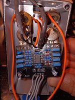
Hello, I am new here. I have built a few pedals point to point but not with a pcb. I will consider myself a newbie at this point since I can't seem to get this working. I have replaced some of the off board wiring that has since broken from moving it too much 😵‍💫
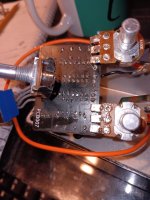
I found that my voltage at the op amp is about 9v at pin 8, 0 at pin 4, about 2.5v at pin 2. All other pins are 7.49 to 8v. I will get the exact voltage tomorrow if needed.

I get about 9v at the junction of R11 and R12. 9v both sides of D5. So no bias voltage after the voltage divider if I am saying that correctly. Nowhere on the board.
I have since replaced C9 since it had a bad connection and I thought maybe I damaged it. Voltage also almost 9v at the positive side.

Anyway, the bypass works, the led comes on, but no sound. I used an audio probe and had a signal until C1 but nothing after. I also reflowed joints and cleaned the board.
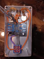
I am fairly certain its my own doing, but need some help to figure it out please. I just want to get it working and then clean up some of the wiring. Thanks for any suggestions.

Sean
 

Attachments

  • 20231005_135129.jpg
    20231005_135129.jpg
    502.4 KB · Views: 26
  • 20231005_134957.jpg
    20231005_134957.jpg
    463.5 KB · Views: 26
  • 20231005_184810.jpg
    20231005_184810.jpg
    444.1 KB · Views: 26
Measure the voltage on both sides of R11.

If you have 9V on both sides there is an open connection (bad solder connection, damaged trace, etc), somewhere between R11 / R12.
 
Just to rule out another possibility, I will say that I've had problems before with using just electrical tape as a protective layer for potentiometers under the PCB. Sometimes the leads on the PCB side are sharp enough to poke right through that soft tape and cause a short.

Good job on using the audio probe. I'd also look at C1 and find out what's keeping the signal from getting to pin 3 of the IC. (Verify that C1 is 10nF, etc)
 
Awesome thanks for getting me started so fast guys! 8.9V going into R11 and 7.49V coming out. Should be about 4.5V at the junction to R12 correct? I will check it out tomorrow and report!

Yes the electrical tape, I plan to change all 3 pots and maybe an insulated one for the tone. For testing I have had it bent away. But great suggestion. There could be more than one issue.

Thank you!
 
So I checked continuity in diode mode following from C10 + to pin 8 of the IC, and to R11 and all seem to zero out. Then I checked the other side of R11 to R12 and also to C9 positive. C9 negative and pin 4 to ground seems good also.

Maybe at least this verifies the traces are not damaged and solder joints are most likely ok? Possible that R11 or R12 are bad or maybe C10? Usually not the component and more likely my work that caused it I realize.

Too bad I soldered the IC in, I ran out of sockets and got overconfident ..ugh! Lesson learned.
 
R10 & R8 are in the wrong order!
I saw that in two other threads before I posted actually. I got excited because I thought that was it! I might have an updated board that reversed it from the previous. But I checked again to make sure.

I confirmed that R10 is going to C7 and also the Out pad. And R8 is going to pin 3 of the tone pot and up to the clipping and pin 7 of the IC.

Thank you for your input! I appreciate it.
R10 - 1M = Brown, Black, Black, Yellow, Brown should be going to C7 & Out pad.
R8 - 1K = Brown, Black, Black, Brown, Brown should be going to Tone 3 pad & IC Pin 7
As you have quoted, it appears to match your trace on the Board.
 
I did and sloppily at that.

Could the pots cause this?? It seemed to measure out and respond but its been in the back of my mind that there is something wrong with the drive pot also.
 
Yes absolutely, no electrical tape.

One question. Looking at the schematic, would pin 3 of the drive pot connect to the other side of C5 for the purple circle in the diagram? I do have continuity there.

Don't get me wrong, I greatly appreciate the help! Just trying to learn.
 
Yes absolutely, no electrical tape.

One question. Looking at the schematic, would pin 3 of the drive pot connect to the other side of C5 for the purple circle in the diagram? I do have continuity there.

Don't get me wrong, I greatly appreciate the help! Just trying to learn.
You are correct, You are learning quickly!
Picture amended!
It seems your traces are all good in those areas!
 
Last edited:
Cool thanks! Still a great diagram, incredibly helpful. I may change some components even though I tend to make a mess. When/if I get this working I will build another.

Maybe I'm in the small percentage that has a bad resistor!
I appreciate all the help!
 
Cool thanks! Still a great diagram, incredibly helpful. I may change some components even though I tend to make a mess. When/if I get this working I will build another.

Maybe I'm in the small percentage that has a bad resistor!
I appreciate all the help!
I've built around 150 pedals & never had a bad resistor.
What else did you remove or replace, I would lean more towards a damaged trace or bad solder joint.
 
Since the first fire up, to the time I posted here, no components replaced outside of the volume pot you noticed. I broke a few wires after coming here for help though.

Today I replaced R11/R12, C9 and C10. Point taken 🙏. Same problem.

On to the test!! Thanks
 
Since the first fire up, to the time I posted here, no components replaced outside of the volume pot you noticed. I broke a few wires after coming here for help though.

Today I replaced R11/R12, C9 and C10. Point taken 🙏. Same problem.

On to the test!! Thanks

Updated !
Power Unplugged!
Try this Continuity Test, hopefully we find something
I would like the Voltage on the OpAmp Pins?:
Audio Continuity Test.jpg 1696727150234.png
 
Last edited:
Back
Top