Broad overly simplified and under-researched FV-1 question

Danbieranowski

Well-known member
Having an issue with distortion in the Pythagoras-based Threeverb. I’ve read about the issue and it looks like it could be the Crystal or the surrounding cap. Before I go chasing things down, if anyone has experience with this, am I on the right track?

Heres where I gathered the limited info I have: http://www.spinsemi.com/forum/viewtopic.php?t=635

And here’s what the pedal sounds like:
 
Is this a pedal that previously worked and now has issues? Or is this an issue with a new build? I would take a close look at the connections for the parts in the audio path and reflow anything remotely suspicious.
 
Are you sure the signal is clean at the FV-1 input?

If you have a scope, you can check the FV-1 clock on pin 9.

The other obvious things to check are Vref, the DC voltage on pins 1 & 7 of the opamps and the 3.3V power.

Like zgrav says, a visual inspection may very well find the problem. Was the FV-1 installed when you received the board, or did you solder it?
 
Last edited:
Are you sure the signal is clean at the FV-1 input?

If you have a scope, you can check the FV-1 clock on pin 9.

The other obvious things to check are Vref, the DC voltage on pins 1 & 7 of the opamps and the 3.3V power.

Like zgrav says, a visual inspection may very well find the problem. Was the FV-1 installed when you received the board, or did you solder it?

FV-1 was preinstalled. It was a new build that just had some weird behavior and I didn’t want to fully unhouse it if it was just the in/out or footswitch, so I fully replaced the footswitch and the 3pdt breakout board. Now when I kick it in the reverb turns on for a second and immediately fades out. I don’t have a scope or anything so I’m just gonna rig up a probe and see how things go following the signal path like suggested by @zgrav recommended.
 
Pulled it out of the enclosure and used a probe on it and can’t replicate the problem. Maybe something shorting in the enclosure but I can’t figure out what. Gonna do a little digging. Also check out the awesomeness that is my essential tremor in my hands while I try to do this stuff lol. Can be a real pain in the ass.
 
Okay I need someone to do a sanity check for me.
The following WORKS.
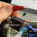
If I connect my audio probe (an alligator clip connected to the sleeve of a 1/4” cable and an alligator clip connected to the tip of the 1/4” cable with a 10nf capicator on the end) to the legs of my output Jack, and plug the other end into the amp, it works. So the signal at least to the output Jack itself is good. Unless I’m an idiot and overlooking something simple, which is totally possible.
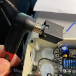
If I plug into the actual output Jack with a cable into the front of my amp it only works in bypass. Once I switch the circuit on, no audio comes through other than the instant the effect is switched on, there is audio for a very short moment, then a tail of reverb and silence. SO, the reverb works great when I’m using a probe attached to the legs of the output Jack. But it doesn’t work when a 1/4” is plugged into the actual output Jack, other than when it’s bypassed, so the Jack works otherwise it wouldn’t pass signal in bypass. This is so weird.

this is passing signal with the effect engaged or in bypass:
CBB18899-D211-48F5-973D-98898137BC60.jpeg

This only passes signal in bypass:
0354D9AA-AC36-4767-AD06-4FCDE49A1CE5.jpeg
I know the Jack works Bc it passes signal in bypass. I know the cable works Bc it passes signal in bypass. But if I use the probe connected to the ground and output of the actual output Jack it passes signal when engaged AND bypassed.
 
Are you sure the signal is clean at the FV-1 input?

If you have a scope, you can check the FV-1 clock on pin 9.

The other obvious things to check are Vref, the DC voltage on pins 1 & 7 of the opamps and the 3.3V power.

Like zgrav says, a visual inspection may very well find the problem. Was the FV-1 installed when you received the board, or did you solder it?
Please see my last response with photos of the probe vs the actual output Jack. Super weird!
 
Is this a pedal that previously worked and now has issues? Or is this an issue with a new build? I would take a close look at the connections for the parts in the audio path and reflow anything remotely suspicious.
Also want to tag you in this to see my last post with photos of the probe on the output Jack vs the actual 1/4 out to see your thoughts.
 
I had a problem like this it turned out to be I had a bad cable. Also could be something shorting to ground somewhere. Do those jacks have 3 lugs or just two?
Only 2 lugs, and I thought it might be cable but it works fine when the effect is bypassed. Just in case I tried another cable as well but same issue.
 
Output jack should be 0.00V. 4.2VDC will upset the input stage of most tube amplifiers. I'm going to assume that you built the Pythagoras v3 board. Looks like C6 is leaking a LOT of current. What type of cap did you use for C6? MLCC should have very high insulation resistance.
 
Output jack should be 0.00V. 4.2VDC will upset the input stage of most tube amplifiers. I'm going to assume that you built the Pythagoras v3 board. Looks like C6 is leaking a LOT of current. What type of cap did you use for C6? MLCC should have very high insulation resistance.

I used an MLCC, and if I measure the legs of C6 I do get the same 4.2.
On leg 3 of IC5 (marked VREF on the last IC in the signal path) I get 4.37.
On VREF leg 5 of IC1 I get 4.37.
On VREF R6 I get 4.37.

Basically just measured at the last few spots that said VREF and that's what I got. I'm not entirely sure what VREF I should get, but that's what I'm getting.

Should I expect C6 to cut that voltage down to anything that falls after it in the signal chain? Since it doesn't, should I be looking at replacing it in case it's a bad capacitor? I have plenty of extras (also MLCC).
 
Vref should be 1/2 of the voltage on pin 8 of IC1 or IC5. There will be some small variation due to component tolerance, meter loading and accuracy. Your 4.37VDC readings are good. C6's purpose is to block the DC coming out from IC5.1. C6 is either shorted or there is a solder bridge on the board. I would do these things:
1. Visual inspection around C6, R20, and the OUT. Look for solder bridges.
2. Remove C6.
3. Measure resistance between the two C6 pads. It won't read infinity, but it shouldn't read zero.
4. Measure the resistance of C6, the one you removed.
5. Power up the pedal and measure the voltage on the output jack. It should read zero. If not, there is still a short somewhere on the board.
6. Once step 5 is successful, install a new C6.
 
Last edited:
Vref should be 1/2 of the voltage on pin 8 of IC1 or IC5. There will be some small variation due to component tolerance, meter loading and accuracy. Your 4.37VDC readings are good. C6's purpose is to block the DC coming out from IC5.1. C6 is either shorter or there is a solder bridge on the board. I would do these things:
1. Visual inspection around C6, R20, and the OUT. Look for solder bridges.
2. Remove C6.
3. Measure resistance between the two C6 pads. It won't read infinity, but it shouldn't read zero.
4. Measure the resistance of C6, the one you removed.
5. Power up the pedal and measure the voltage on the output jack. It should read zero. If not, there is still a short somewhere on the board.
6. Once step 5 is successful, install a new C6.

1. Visual inspection around C6, R20, and the OUT. Look for solder bridges. - No issues here that I can see. Soldering looks clean with no cold joints.
2. Remove C6. - Done.
3. Measure resistance between the two C6 pads. It won't read infinity, but it shouldn't read zero. - On 2000k mode it measures as 239.
4. Measure the resistance of C6, the one you removed. - My multimeter is a garbage $10 one and doesn't have any mode that measures the resistance or anything of either the original or replacement cap. This is my cue to get a better one.
5. Power up the pedal and measure the voltage on the output jack. It should read zero. If not, there is still a short somewhere on the board. - This did read as 0.
6. Once step 5 is successful, install a new C6. - Replaced C6 and now everything works properly.

You are an absolute king. This has been a very educational experience for me, and I owe you a beverage. Thank you for your patience and walking me through the troubleshooting process of this. This is the first time I've encountered a bad component (only started doing this with the quarantine), and tracing the schematic and going through these steps has been an epic learning experience. Thank you!

And thanks everyone else who offered assistance!

-Dan
 
Happy to hear it all worked out. The 2000K range is a resistance measurement. when you measured 239, that was 239K Ohms. Basically sneak paths thru the last two opamps and their surrounding resistors. MLCCs (multi layer ceramic capacitors) are fairly fragile internally. They contain many thin layers of metal and ceramic. Any cracks in the ceramic that form either as latent manufacturing defects or from thermal shock during soldering can lead to shorts.

As for cheap DMMs, the main one I use on my bench is a freebie from HF. It does the job and I don't feel bad if solder gets splashed on it. I also have a good one that I use when the freebie isn't good enough for certain measurements.
 
Back
Top