Can somebody please explain to me how to measure a diode and know if "this will be more compressed"

Barnshart

Member
Hello!

Could somebody simply answer this question for me?

When using a multimeter setting it to simply the "diode" symbol / continuity setting. Will a higher number reading on there indicate more or less compression in a circuit (Rat in this instance), or does the higher number mean less compression?

I have the following diodes and these readings, and I would like to understand how they actually would impact my Rat if I add them into a 3 way toggle


BAT 41: 394

1N60P: 240

1N4148: 708

1N914: 709

Bonus question!

How can I measure a red LED using this method? When I hook it up to the multimeter the way I am with the other diodes, it simply illuminates the LED and gives me no reading. What do I need to do to get an actual measurement from these?

Thank you in advance to anybody who answers!
 
You're measuring their forward voltage, in this case millivolts. The lower the number, the sooner they'll clip and compres. Also, the lower this number is in a hard clipping situation (Rat, for example) they'll also diminish your output volume.
So, the higher the number, the less clipping and compression they'll apply to the signal

Your BAT41s and 1N60s would be good stand-ins for germanium diodes. The others listed are the classic silicon diodes.

When the LED is lit up, you've got it hooked up the right way, but it should be giving you a reading. Typically, LEDs will range from about 1.2vf to 3, depending on color and brightness.

In this hard clipping arrangement, LEDs will be the loudest, and offer more dynamic range. You can also run no diodes for the "Clean" Rat found on the ProCo Deucetone, and get just the opamp's clipping.
 
How can I measure a red LED using this method? When I hook it up to the multimeter the way I am with the other diodes, it simply illuminates the LED and gives me no reading. What do I need to do to get an actual measurement from these?
Look at the data sheets--they will publish the Vf. It might be measured at a different current than what happens in the circuit, but it's good enough for comparing to other diodes.

It might be that your meter only measures diodes up to 1V. LEDs are usually greater than 1 (around 1.7V).
 
Just to muddy the waters, if you want less compression you can use two or more diodes in series going each way to provide clipping. You can use 3 one way against 2 the other to create asymmetrical clipping. I generally use pairs of diodes (IE fours diodes in total) because I prefer less compression. In a Rat I'd probably stick with the single pair but it can be fun to experiment.
 
Look at the data sheets--they will publish the Vf. It might be measured at a different current than what happens in the circuit, but it's good enough for comparing to other diodes.

It might be that your meter only measures diodes up to 1V. LEDs are usually greater than 1 (around 1.7V).
Just for an example for me, 1N60P says 240mV at 1 mA and 650mA at 30mA-200mA. So is in between those a good number to use to compare? Or would you use the higher number, since dirt pedals are ~100mA?
 
Just for an example for me, 1N60P says 240mV at 1 mA and 650mA at 30mA-200mA. So is in between those a good number to use to compare? Or would you use the higher number, since dirt pedals are ~100mA?
I'm not sure--I think most drive pedals are around 10mA.
 
FOR REFERENCE, SOME FORWARD VOLTAGES (Vf IF = 1 mA ):

FV TYPE
0.2V - Schottky
0.3V - Germanium
0.45V - BAT 41
0.7V - Silicon
1.7V - Red LED
2.1V - Yellow LED
2.2V - Green LED
3.6V - Blue LED

5mm IR LEDs have a forward voltage requirement of 1.2v to 1.6v DC and normally the Typical Forward Voltage to apply is 1.4v

~790mV -- 1N4148 (Silicon) [.65v, Max 1v according to Vishay datasheet]
~265mV -- 1N60 (Germanium)
~1700mV -- LED (red)
~205mV -- Schottky 1N5819
~740mV -- 1n4001 (Silicon)
- BAT42: ~280mV
- LED: ~1700mV (actually varies with the color)


Everything else falls in between:

- 1N34A (germanium): ~ 340mV
- BAT41: ~ 370mV
- 1N400X series: ~500mV
- 1N4148/1N419 ("standard" silicon): ~600mV
- many transistors (including mosFET's): ~720mV


From Jack Orman, some zener diodes and their breakdown voltages:

1N4742 1.2v
1N5221 2.4v
1N5222 2.5v
1N5223 2.7v
1N5224 2.8v
1N5225 3.0v
1N5226 3.3v
1N5227 3.6v
1N5228 3.9v
1N5229 4.3v
1N5230 4.7v

Check out Jack Orman's AMZ site and blog for more cool info about MOSFET clipping (and others) and his warp controls.

ALSO check out the wealth of info from RG Keen.

Mark Hammer's info is a little more spread out across the DIY forums.


Furthermore
1N4001 If: 1

A regular 1N4148 silicon diode has a forward drop of about 0.65V, quite a bit when supplies are 2..3V! The Schottky diode has a much lower voltage drop. It's usually specified as 0.3..0.4V, but it really depends on the amount of current passed through it.


If you search through google images of LED clipping (and other types of clipping) you'll get some neat graphs with a visual representation, such as this one:

ihz3udv.png


Lots of graphs online like the one above, some are smaller simpler with less diodes or all LED colours etc. Start broad and then narrow it down to include "fV" or "forward voltage" and "clipping" in your search criterium(s).

Info provided above is not set in stone, due to variables in an imperfect universe.
 
PS:
LEDs CLIPPING INFO http://www.diystompboxes.com/smfforum/index.php?topic=85219.0


colorvoltage (Volts)
IR1.5
red2.0
orange2.0
yellow2.1
green2.2
true green3.3
blue3.3
white3.3
UV3.3
blue (430 nm)4.6


The 5mm diffused red and 5mm diffused green LEDs I have here clip at 1.8V for the red and 2.6V for the green. So the green LEDs are going to give you more headroom on the gain knob enabling you to get more clean boost. I don't think you'll perceive any difference it the tonality of the clipping. When I've compared different color LEDs by ear, they sound pretty much the same once you normalize the gain and volume.


MARK HAMMER ON MULTIPLE LEDs in SERIES
You're getting clipping on one half cycle of the signal, but most likely nothing on the otherhalf cycle...or at least nothing that crops up for more than a few miliseconds here and there. A pair of LEDs in series represents a forward voltage that could easily be in the 3V+ range. A stock TS applies a maximum gain of 118x. Divide our hypothetical 3000mv threshold by 118 and at max gain that half cycle of the signal would need to be at least 25mv (i.e., p-2-p > 50mv) in order to be clipped. Not that many guitar signal remain above that point for very long. True, they CAN produce peaks much greater than that, but those peaks don't really last all that long during the entire lifespan of the picked note.


For reference, the typical 1N914s clip at around 0.7V.


Some other LEDs:
5mm diffused orange 2.0V
5mm diffused yellow 2.1V
5mm clear blue 3.3V
5mm clear white 3.5V


M HAMMER: The LED colour with the lowest clipping threshold (around 1.5v) is red, and is approximately equal to using three 1N914 diodes in series for each direction [BMPOA!]. Other colours, because of the different composition, have higher thresholds.


10 :: 5mm RED WATER CLEAR ULTRA BRIGHT :: TAYDA A-706
Manufacturer: LIGITEK
Emitting colour: Red
Diameter: 5mm
Lens colour: Water Clear
Forward voltage(V): 2.0-2.2
Current(mA): 20
View angle: 25
Luminous intensity(MCD): 8,000 - 12,000

10 :: 5mm BLUE WATER CLEAR ULTRA BRIGHT :: TAYDA A-407
Manufacturer: LITE-ON
Emitting color: Blue
Diameter: 5mm
Lens color: Water clear
Forward Voltage(V): 3.2-3.4
Current(MA): 20
View angle: 20
Luminous intensity(MCD): 12,000 - 14,000

10 :: 5mm WHITE WATER CLEAR ULTRA BRIGHT :: TAYDA A-408
Manufacturer: LITE-ON
Emitting color: White
Diameter: 5mm
Lens color: Water clear
Forward Voltage(V): 3.2-3.4
Current(MA): 20
View angle: 25
Luminous intensity(MCD): 16,000 - 20,000

5 :: 5mm YELLOW :: TAYDA A-1555
Manufacturer: LIGITEK
Emitting color: Yellow
Diameter: 5mm
Lens color: Yellow Diffuse
Forward voltage(V): 2.0-2.3
Current(mA): 20
Luminous intensity(MCD): 2,000 - 3,000

5 :: 5mm GREEN WATER CLEAR SUPER BRIGHT :: TAYDA A-057
Manufacturer: LIGITEK
Emitting color: Green
Diameter: 5mm
Lens color: Water Clear
Forward voltage(V): 3.2-3.4
Current(mA): 20
View angle: 30
Luminous intensity(MCD): 8,000 - 10,000

5 :: 5mm GREEN :: TAYDA A-1553
Manufacturer: LIGITEK
Emitting color: GREEN
Diameter: 5mm
Lens color: Green Diffuse
Forward voltage(V): 2.3-2.5
Current(mA): 20
Luminous intensity(MCD): 2,000 - 3,000


20 :: 3mm RED SUPER BRIGHT :: TAYDA AZ-1554
Manufacturer: KENTO
Manufacturer Part No: 5408URC
Illumination Colour: Red
Lens Colour/Style: Red
LED Size: 5mm
Lens Shape: Round
Wavelength/Color Temperature: 620-630nm
Luminous Intensity: 8000 - 10000 mcd
Viewing Angle: 30 deg
Forward Voltage: 1.9 - 2.1 V
Forward Current: 20mA
Maximum Operating Temperature: + 100 C
Minimum Operating Temperature: - 20 C

20 :: 3mm RED :: TAYDA A-261
Manufacturer: LIGITEK
Emitting color:Red
Diameter:3mm
Lens color: Red Diffuse
Forward voltage(V):2.0-2.2
Current(MA):20
Luminous intensity(MCD): 4,000 - 6,000

20 :: 3mm RED WATER CLEAR ULTRA BRIGHT :: TAYDA A-705
Manufacturer: LIGITEK
Emitting color: Red
Diameter: 3mm
Lens color:Water Clear
Forward voltage(V): 2.0-2.2
Current(mA): 20
View angle: 20 - 25
Luminous intensity(MCD): 4,000 - 6,000

10 :: 3mm GREEN :: TAYDA A-262
Manufacturer: LIGITEK
Emitting color: GREEN
Diameter: 3mm
Lens color: Green Diffuse
Forward voltage(V): 2.3-2.5
Current(mA): 20
Luminous intensity(MCD): 2,000 - 3,000

5 :: 3mm YELLOW :: TAYDA A-263
Manufacturer: LIGITEK
Emitting color: Yellow
Diameter: 3mm
Lens color: Yellow Diffuse
Forward voltage(V): 2.0-2.3
Current(mA): 20
Luminous intensity(MCD): 2,000 - 3,000

10 :: 3mm BLUE WATER CLEAR ULTRA BRIGHT :: TAYDA A-406
Manufacturer: LITE-ON
Emitting color: Blue
Diameter: 3mm
Lens color: Water clear
Usage voltage(V): 3.2-3.4
Current(MA): 20
View angle: 20 - 25
Luminous intensity(MCD): 18,000

10 :: 3mm GREEN WATER CLEAR SUPER BRIGHT :: TAYDA A-064
Manufacturer: LIGITEK
Emitting color: Green
Diameter: 3mm
Lens color:Water Clear
Wavelength: 515 - 520 nm
Forward voltage(V): 3.2 - 3.4 V
Current(mA): 20
View angle: 20 - 25
Luminous intensity(MCD): 10000 - 12000 mcd

10 :: 3mm WHITE WATER CLEAR ULTRA BRIGHT :: TAYDA A-2226
Manufacturer: LIGITEK
Emitting color: White
Diameter: 3mm
Lens color: Water clear
Forward Voltage(V): 3.2-3.4
Current(MA): 20
View angle: 25
Luminous intensity(MCD): 14,000 - 16,000

10 :: 3MM ORANGE WATER CLEAR :: TAYDA A-4571
Manufacturer: LIGITEK
Emitting color:Orange
Diameter:3mm
Lens color: Water Clear
Forward voltage(V):1.8-2.0
Current(MA):20
Luminous intensity(MCD): 4,000 - 6,000

10 :: 3mm ORANGE :: TAYDA A-264
Manufacturer: LIGITEK
Emitting color: Orange
Diameter: 3mm
Lens color: Orange Diffuse
Forward voltage(V): 2.0-2.3
Current(mA): 20
Luminous intensity(MCD): 2,000 - 3,000
5 :: 3mm RED :: WECL L10 13-01-0201


10 :: 3mm GREEN :: WECL L11 13-01-0202


5 :: 3mm YELLOW :: WECL L12 13-01-0203
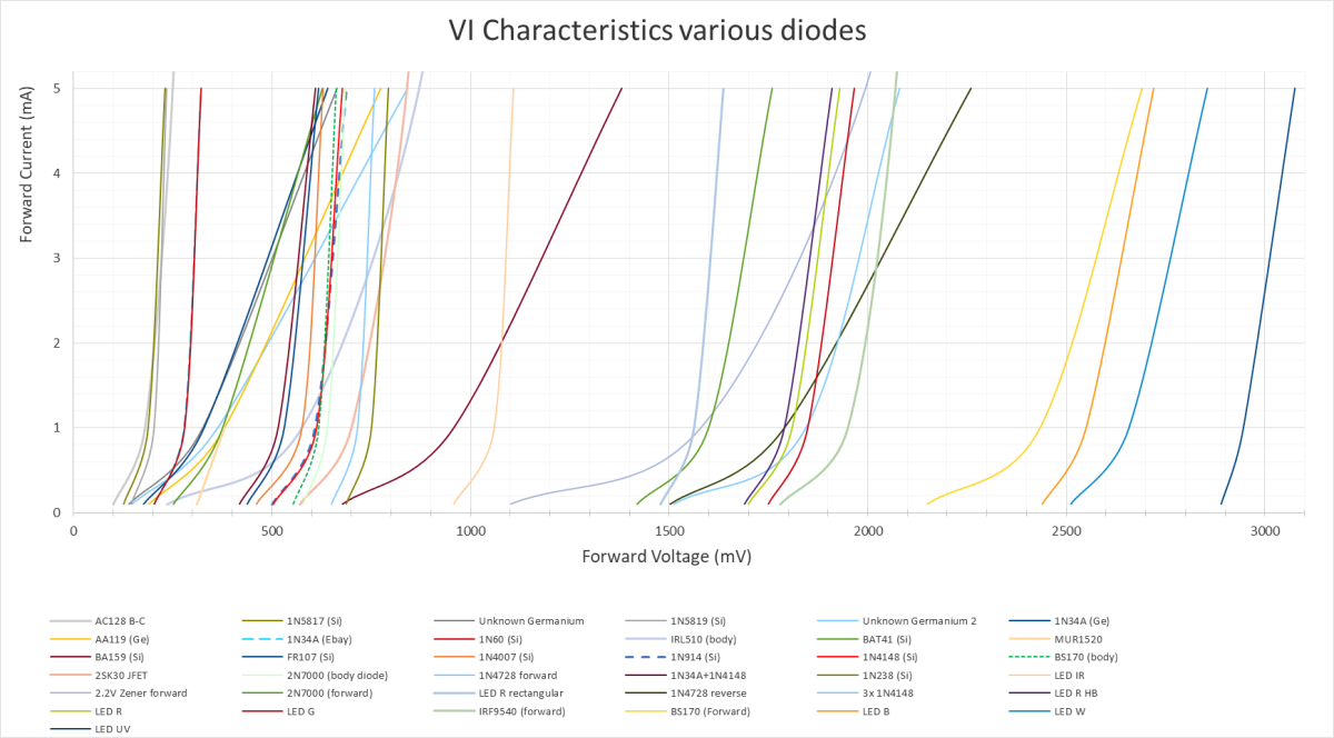
 
Vf is meaningless if you don't know the corresponding forward current (If). In a Rat, If is limited to around 3mA or so when using 1N4148s. It's significantly less when using LEDs.

Also, hard clippers like the Rat don't much care about leakage. Soft clippers, like the Timmy, BMP, TS, etc. are very sensitive to leakage and in many cases the leakage in one diode is so high the the parallel diode never gets to do any clipping. My point is that comparing Si to Ge in clippers can often be an apples & oranges situation.
 
The reason we use diodes for clipping is because of the non-linear relationship between forward current and forward voltage. We need to have a plot of voltage vs. current for the specific part # we're using in order to predict its behavior in a circuit.
 
Back
Top