Captain Bit- Low Level Distortion

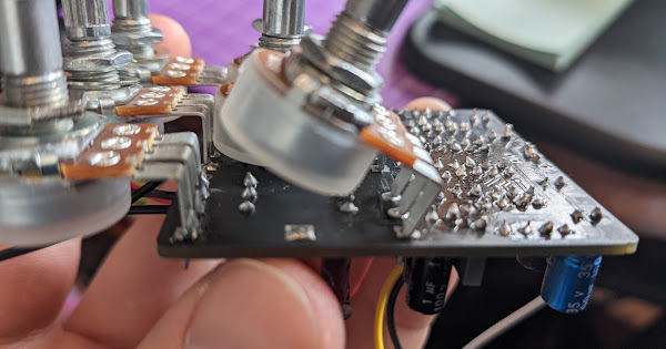
Just finished up the Captain Bit build and testing on the auditorium board. I have signal passing, but its LOW level and only distorted. Seems that the pots have zero effect on the output signal. Looked over my solder joints, components, etc. and nothing standing out. About to get the probe out and see if I can track it down, but wanted to see if anyone has run into something similar. Thanks in advance.
 
Finally got my probe replaced. I have good audio at leg 2 of A100k pot which seems to be the last place before heading to output, but no signal on output pad at bottom of PCB....huh. What in the world could that be?


1615241728493.png
 
Last edited:
@Chuck D. Bones maybe you have some insight. See the video above (and schematic above that). I have signal at leg 2 of A100k, but nothing at output pad of PCB. I unsoldered it and cleaned off pad, same result. You are always helpful...thanks in advance for any thoughts!
 
check the connectivity between the pad for leg 2 of the A100K pot and the output pad on the board. if you have have a good connection it means you probably also have an "extra" connection to another part or to ground that is draining your signal. if you are showing some high resistance between those two places you need to look for a break in your path between them.
 
check the connectivity between the pad for leg 2 of the A100K pot and the output pad on the board. if you have have a good connection it means you probably also have an "extra" connection to another part or to ground that is draining your signal. if you are showing some high resistance between those two places you need to look for a break in your path between them.
No continuity between those two points.
 
The schematic shows that you should have continuity between pad 2 of the level pot and the OUT pad that connects to your footswitch. Look closely at both sides of your PCB to see if you can find a spot where the trace connecting those two points might have been broken. You can post a detailed picture of each side of your PCB if you want suggestions on where to check. . Go ahead and reflow the solder connections on your level pot and where the wire connects to your OUT pad.

Those suggestions are the best way to isolate the cause of the problem. Finding that and fixing it that way may also fix another related problem that you don't even know you have right now. But if you want to try a shortcut to see if it fixes the problem and find out if you have any other issues, you could take an insulated wire and connect it from terminal 2 of the level pot to your footswitch where the OUT pad connects to it. If that works out OK, you might just want to call it a day. Or you could then try to find the break in continuity on you PCB and fix it there instead of having that jumper wire in place.
 
Take that blue wire going to the OUT on your test board and touch it to the second terminal on the A100K pot. It that works -- which seems likely, just run a wire from terminal 2 up to the connection on your footswitch where the OUT wire from the PCB would go.
 
Take that blue wire going to the OUT on your test board and touch it to the second terminal on the A100K pot. It that works -- which seems likely, just run a wire from terminal 2 up to the connection on your footswitch where the OUT wire from the PCB would go.
yeah, that's my next move. I had to do something similar when I fried a pad on a Vanquisher fuzz I built. Bad trace ya think?
 
Given comments from a couple of other builders saying they have a similar issue, that might be the case. If so, it will be great if you can nail down an easy fix for everyone. The sounds you were getting from the middle lug on your A100K pot sounded like what you should be getting at the output.
 
Back
Top