Will This Work? (3PDT PCB Question)

Ginsly

Well-known member
I’ve used these 3PDT pcbs with stripboard builds, and they work great:
1D8C589C-C4CB-442B-AEDE-C7EE2EE25A77.jpeg

I’m a little confused about how to use them with PedalPCB boards- if that’s even possible.

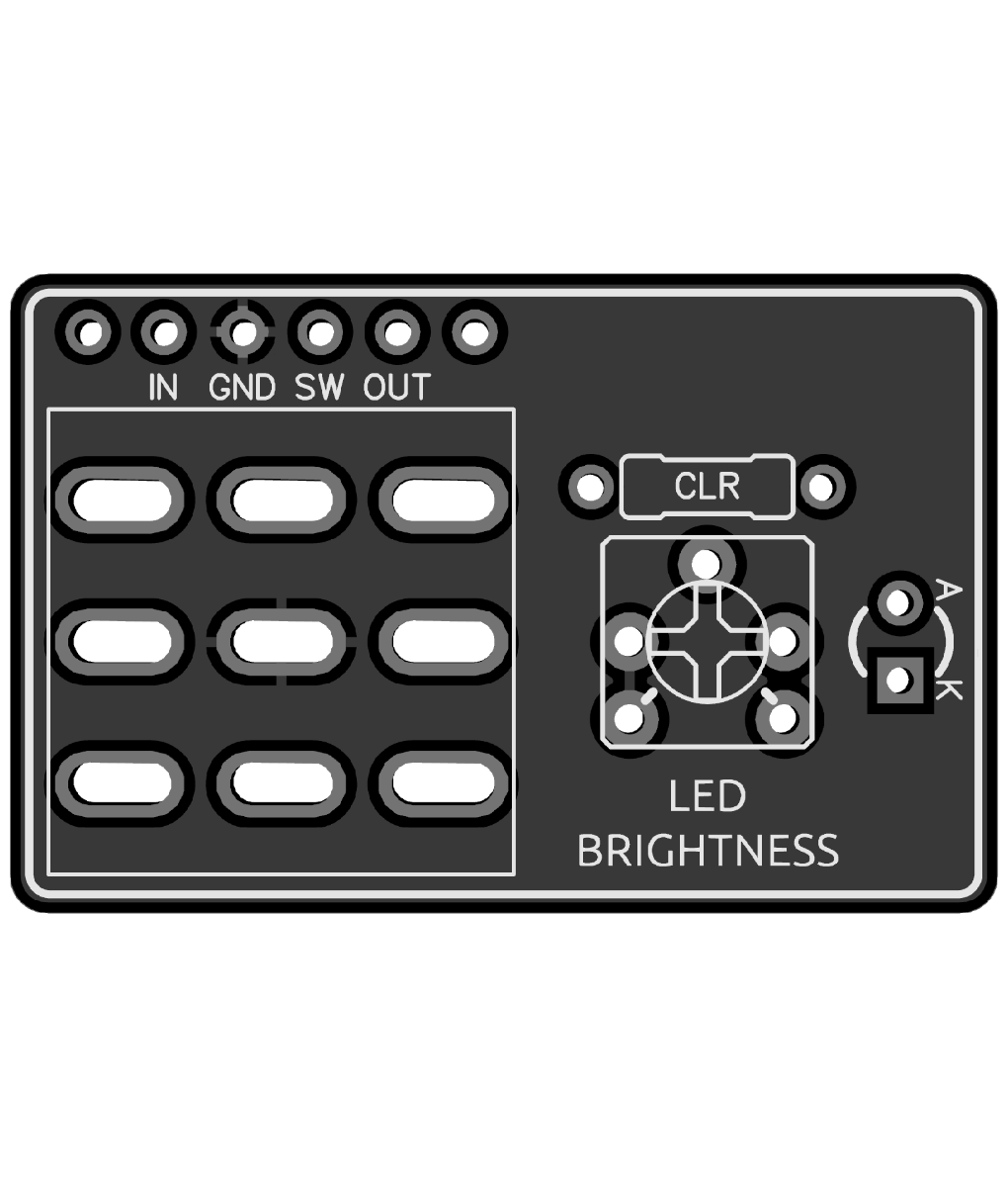
- in order to use the footswitch pcb for mounting the CLR & LED, it sounds like I need to jumper the CLR pad on the main PPCB as well as the LED pads.

- I’ll still connect In and Out at the bottom of the main pcb to the corresponding pads on the footswitch pcb. Do I need to connect ”SW” on the main pcb to “L” (led) on the 3pdt pcb?

- at this point, it looks like I have to connect the “9v(+)” and its “Ground(-)” at the TOP of the main pcb to “9v” and “G” on the 3pdt pcb. Do I leave ground “G” on the bottom of the main pcb open? Seems like there’s no place to connect it to the 3pdt… Then I’ll connect the DC jack to the side of the 3pdt pcb as shown in the picture- the way I do it with stripboard. Please correct me if I’m wrong.

- can I then connect both Tip and Ring of the Jacks to the corresponding footswitch pcb pads and leave the two Ground (sleeve) connections at the top of the main pcb open?

- I also use DC switching jacks since I install battery snaps. I connect black to Ring on the Input Jack and red to the middle DC Jack lug. Figured I’d mention it in case it was an issue here.

I realize I can just use PPCB footswitch boards, some of which have led pads. If I HAD to use this footswitch pcb with a PPCB project- could I? I’m pretty new to building, so this may help me understand more than the topic at hand. Thanks much!
 
@jwin615 I just moved this over here since I marked the Dim Bypassed LED thread "solved". So it sounds like in most cases with a PPCB-type board, I would NOT want to hook anything up to the 3PDT board's power pads, but rather use the + and - at the top of the board for safety reasons. Then I can install a battery snap as usual to the DC Jack's middle lug and the Input Jack's ring. I would love to use the fs board for the DC jack, but if you think it's risky I'll stay away! Mostly building fuzz, fwiw.

If I'm using the 3PDT board to connect Tip & Ground for both In and Out jacks, I can simply leave the Ground pads at the top of the main pcb open. Jumper LED and CLR on the main board, and connect everything as usual other than "SW" on the main board connecting to the 9V pad on the 3PDT. The LED pad at the top of the 3PDT board is left empty, since the CLR and LED are already on the 3PDT board. This look right (below)? @Robert will I fry your boards by doing this?? Ha... I'll normally use the PPCB footswitch boards of course, but there are times when it makes sense for me to use the fs board for LED/CLR and I/O jacks.

Using3PDTpcbWppcbPCB2.png
 
Last edited:
Nope, that's exactly how this is used:
Ah! Fantastic! Yep those look great. Nice that they're adjustable.

The ones I have are a bit different, what with the pads for I/O jacks and power pads, but it sounds like if I stick to the latest diagram I posted I'll be ok. I would have never thought that SW would wind up connecting to "9V" on the blue footswitch board I posted rather than "LED", but it sounds like that's correct.

I would have also assumed it would be ok to use the footswitch board's power pads rather than the main pcb's, but I'd rather not do anything risky. I'm really just building silicon fuzz (no charge pumps or anything), so it sounds like it could be ok for those circuits...
 
... I marked the Dim Bypassed LED thread "solved"
...

Please edit your post as above to include a link to the thread mentioned. Cross-referencing helps when trouble-shooting, modding, etc.
Did I link the correct thread?

I'm curious about how you're using the off-brand 3PDT daughterboards with PPCB main boards.

Whether you jumper anything depends on whether you're using the main-board's LED or going to use the daughterboard's LED.
Same goes for the CLR; everything depends on what you're doing and how you're using things.
 
@Feral Feline Done!

I mention it in previous posts, but there are times when I'd like to connect In/Out Jacks (inc Ground/Sleeve), LED and CLR to a 3PDT pcb rather than the main circuit pcb. I'd like to connect the DC Jack there too, but it sounds like that could present problems with certain circuits (charge pumps, etc).

Some of this comes down to how I box up some PPCB boards; I typically add a 9v battery snap to the DC Jack and (Stereo) Input Jack Ring, which makes the top jacks tougher to fit, even in a 125B. I also use non-pcb-mounted pots sometimes, as it allows me to shove the pcb further up; I need to do that since the battery at the bottom kinda pushes everything else up a bit. Maybe this sounds ridiculous, and hey, it mostly is. The PCB kinda floats like Vero since the pots don't hold it down; that's one of the reasons I like to mount the LED on the 3PDT board - it stays put. Side jacks are close to the 3PDT switch, so it's nice to connect them there. Same with the DC Jack, but again, sounds like that may not always be a good idea.
 
Doesn't sound ridiculous at all. I've floated boards with all offboard wiring to get the Pot arrangement how I want it, not how the PCB-designer wanted it. Or changing things to fit a graphic on the face of the pedal or... lotsa reasons to do the things we do.
 
Doesn't sound ridiculous at all. I've floated boards with all offboard wiring to get the Pot arrangement how I want it, not how the PCB-designer wanted it. Or changing things to fit a graphic on the face of the pedal or... lotsa reasons to do the things we do.
That's really encouraging to hear, seriously. I actually haven't done a single PPCB boxing setup the "proper" way yet, ha... It sounds like it'd still work with top jacks, as they kind of hover over the back of the top pots (I think..?). If I raise the 3PDT a bit I bet it'd work in certain pedals... Hmm maybe the way I've been doing it is ridiculous after all! Ha..
 
@jwin615 I just moved this over here since I marked the Dim Bypassed LED thread "solved". So it sounds like in most cases with a PPCB-type board, I would NOT want to hook anything up to the 3PDT board's power pads, but rather use the + and - at the top of the board for safety reasons. Then I can install a battery snap as usual to the DC Jack's middle lug and the Input Jack's ring. I would love to use the fs board for the DC jack, but if you think it's risky I'll stay away! Mostly building fuzz, fwiw.

If I'm using the 3PDT board to connect Tip & Ground for both In and Out jacks, I can simply leave the Ground pads at the top of the main pcb open. Jumper LED and CLR on the main board, and connect everything as usual other than "SW" on the main board connecting to the 9V pad on the 3PDT. The LED pad at the top of the 3PDT board is left empty, since the CLR and LED are already on the 3PDT board. This look right (below)? @Robert will I fry your boards by doing this?? Ha... I'll normally use the PPCB footswitch boards of course, but there are times when it makes sense for me to use the fs board for LED/CLR and I/O jacks.
looks good from my house
 
Back
Top