radioteacher
New member
Thank you in advance for helping me with this issue.
I am currently testing the Closed Circuit Booster Limiter.
It sounds great. The only issue is really minor. The LED does not light when on. How can the pedal work and not the Power LED?
When powered, I do have 9 volts on the LED Anode and when unpowered have continuity from LED Anode to +9 at the power jack.
From the LED Cathode I have continuity to R100 (4.7k) at the lead near the IC.
When testing across the resistor R100 I get 4.7k and I get the same reading(4.7k) at point SW on the footswitch pcb.
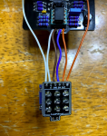
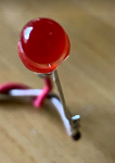
The side with the flat spot in the LED, that has the short lead (cathode) is connected to the brown wire that goes to the K point on the pcb. I tested the LED and it lights in the tester.
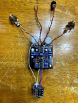
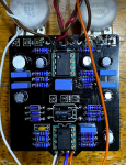
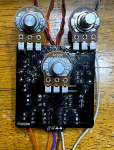
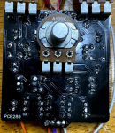
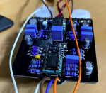
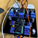
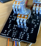
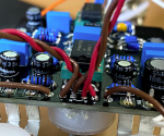
In the photos, I spotted a cold solder joint on one end of C102. I am going to take care of that.
I have stocked up on parts that provide cleaner audio paths including all-new NPO caps and better resistors since my Propolis photo here.
-RT


