MichaelW
Well-known member
This pedal is the result of the work of the "Pedal Triumvirate", @Chuck D. Bones design, @cooder's board layout, and @fig's generosity, procurement, distribution and chip programming!
When I built the Cattle Driver board I was prattling on and on about how much I liked it. (It's still sitting in my chain, still love it! )
)
@Chuck D. Bones mentioned that I should check out his Mosfet drive breadboard project since I liked the Cattle Driver so much.
One thing led to another and before long I had a board for Chuck's project and all the special bits and bobs for it from our resident philanthropist @fig!
I think I mentioned in another thread somewhere that I got my double whammy boosters yesterday (Moderna + Flu) and while it didn't mess me up as bad my last booster, I found myself wide awake and unable to sleep at 4am this morning. So what does one do at 4am on a Saturday unable to sleep? Brew a pot of coffee and build a pedal of course! hahaha.
Like the Cattle Driver and the PedalPCB Mosfet Driver, this is a "tube-like" overdrive/distortion pedal that uses mosfets for the gain stages in place of tubes.
The Cattle Driver (Buffalo TD-X) and the Mosfet Driver were designed to emulate the Butler BK Tube pedal. The Cowpoker takes the concept a lot further and has @Chuck D. Bones sonic fingerprints all over it! Meaning TONS of gain hahaha. Much like the Mojito Deluxe the gain is very thick and chewy. If you liked the Mojito then you'll definitely like this circuit.
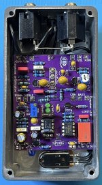
@cooder's board layout has a lot of cool trick elements in it like built in soft relay bypass switching, pads for a compensation cap if you want to experiment with other opamps besides the prescribed ones, optional SMD relay switching PIC (if you have the tools and ability to program it that is) all packaged up in a nice neat, efficient layout.
There's also a bit of "sussing out" some stuff as there are no build docs or anything like that.
So anyway, I finished the pedal fairly quickly......aaaaaannddd it didn't work. After exhausting all of my troubleshooting skills....(in about 5 minutes) I reached out to Chuck for help. He walked me through some troubleshooting steps and it turns out the programming on the PIC for the relay was corrupted and causing the problem. I popped in another PIC chip that @fig had sent me and voila! Fired right up and just about took my face off. (Did I mention this thing has a lot of gain? )
)
I've been messing around with it on a bunch of different guitars and tweaking a couple of things and I think it's done now, back cover has been signed, dated and screwed on. Thanks so much for the troubleshooting help @Chuck D. Bones!
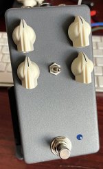
Sounds really good with single coils, P90's and hum buckers. There's a "Voice" toggle that brings in either a 47u or 2u2 cap for more shades of aggression in the gain. Helps with compensating for different pickup/guitar/amp combinations. I'm finding I like it best in the middle position with the gain just barely cracked, sounds great with my Strat in that setting. Diode clipping is provided via a pair of LED's. I used 3mm green diffused LEDs from Amazon (Chanzon brand) that measured ~1.95v Vf on my tester. The board and schematic calls for an LF356N op amp, which I didn't have. But I did have some LF351N's which work just fine. I also tried a TL071 in it as well and don't hear a lot of difference. So the LF351N is back in it now. The gain pot calls for an A500k. I didn't have a PCB pin one on hand so I hacked an A1M with a parallel resistor. I may go back and change this, as the taper feels a bit off with the hack on this pedal.
There's also an internal gain trimmer for even MORE gain if desired. I have mine set to the lowest setting. There's still tons of gain on tap with it turned all the way down.
So if you're building this pedal, couple lessons learned I can pass on.
1) Don't bias voltages using the bias pad on the board. As Chuck told me, that only biases the opamp. You want to use the Drain leg of the BS170's to set the bias of Q1 and Q2. Target 5.5v then fine tune by ear. Since there's only one voltage trimmer, you'll wind up splitting the difference between Q1 and Q2. I have my Q1 at ~5.45v and Q2 at ~5.65v. Getting the transistors biased to this range definitely smooths out overall texture of the gain. Although you can go off script and tune it to sound more angular and aggressive as well.
2) Ignore the SMD pads for the TLP222A. That's an either/or choice for the relay PIC chip (IC-2). Since @fig already did all the heavy lifting with providing programmed PIC chips you won't need to worry about this.
3) If you're using an LF351N, LF356N, or TL071 opamp (as recommended) you can ignore "comp" capacitor pads. (Right under IC1) These pads are only if you're going to go off script and try to use a single channel opamp IC that doesn't have built in compensation in which case @cooder has made the provision for you to add a small cap without having to hack the IC legs. (Very nice stuff!)
4) There's an oddball value cap for C13. (3u3 film). This value is not strictly necessary. As per Chuck you an use 1u, 2u2 as well. I took his suggestion and used a 2u2 Tantalum cap (orientation is not marked. Positive leg furthest away from the volume put. Negative leg closest to the volume pot)
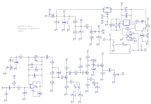
5) Use the most recent schematic as there are some small tweaks that have been made than the one in the thread I linked above. (attached below)
6) Thank @fig for his great generosity, @Chuck D. Bones for another excellent design and @cooder for another great board layout!


When I built the Cattle Driver board I was prattling on and on about how much I liked it. (It's still sitting in my chain, still love it!
@Chuck D. Bones mentioned that I should check out his Mosfet drive breadboard project since I liked the Cattle Driver so much.
One thing led to another and before long I had a board for Chuck's project and all the special bits and bobs for it from our resident philanthropist @fig!
I think I mentioned in another thread somewhere that I got my double whammy boosters yesterday (Moderna + Flu) and while it didn't mess me up as bad my last booster, I found myself wide awake and unable to sleep at 4am this morning. So what does one do at 4am on a Saturday unable to sleep? Brew a pot of coffee and build a pedal of course! hahaha.
Like the Cattle Driver and the PedalPCB Mosfet Driver, this is a "tube-like" overdrive/distortion pedal that uses mosfets for the gain stages in place of tubes.
The Cattle Driver (Buffalo TD-X) and the Mosfet Driver were designed to emulate the Butler BK Tube pedal. The Cowpoker takes the concept a lot further and has @Chuck D. Bones sonic fingerprints all over it! Meaning TONS of gain hahaha. Much like the Mojito Deluxe the gain is very thick and chewy. If you liked the Mojito then you'll definitely like this circuit.
@cooder's board layout has a lot of cool trick elements in it like built in soft relay bypass switching, pads for a compensation cap if you want to experiment with other opamps besides the prescribed ones, optional SMD relay switching PIC (if you have the tools and ability to program it that is) all packaged up in a nice neat, efficient layout.
There's also a bit of "sussing out" some stuff as there are no build docs or anything like that.
So anyway, I finished the pedal fairly quickly......aaaaaannddd it didn't work. After exhausting all of my troubleshooting skills....(in about 5 minutes) I reached out to Chuck for help. He walked me through some troubleshooting steps and it turns out the programming on the PIC for the relay was corrupted and causing the problem. I popped in another PIC chip that @fig had sent me and voila! Fired right up and just about took my face off. (Did I mention this thing has a lot of gain?
I've been messing around with it on a bunch of different guitars and tweaking a couple of things and I think it's done now, back cover has been signed, dated and screwed on. Thanks so much for the troubleshooting help @Chuck D. Bones!
Sounds really good with single coils, P90's and hum buckers. There's a "Voice" toggle that brings in either a 47u or 2u2 cap for more shades of aggression in the gain. Helps with compensating for different pickup/guitar/amp combinations. I'm finding I like it best in the middle position with the gain just barely cracked, sounds great with my Strat in that setting. Diode clipping is provided via a pair of LED's. I used 3mm green diffused LEDs from Amazon (Chanzon brand) that measured ~1.95v Vf on my tester. The board and schematic calls for an LF356N op amp, which I didn't have. But I did have some LF351N's which work just fine. I also tried a TL071 in it as well and don't hear a lot of difference. So the LF351N is back in it now. The gain pot calls for an A500k. I didn't have a PCB pin one on hand so I hacked an A1M with a parallel resistor. I may go back and change this, as the taper feels a bit off with the hack on this pedal.
There's also an internal gain trimmer for even MORE gain if desired. I have mine set to the lowest setting. There's still tons of gain on tap with it turned all the way down.
So if you're building this pedal, couple lessons learned I can pass on.
1) Don't bias voltages using the bias pad on the board. As Chuck told me, that only biases the opamp. You want to use the Drain leg of the BS170's to set the bias of Q1 and Q2. Target 5.5v then fine tune by ear. Since there's only one voltage trimmer, you'll wind up splitting the difference between Q1 and Q2. I have my Q1 at ~5.45v and Q2 at ~5.65v. Getting the transistors biased to this range definitely smooths out overall texture of the gain. Although you can go off script and tune it to sound more angular and aggressive as well.
2) Ignore the SMD pads for the TLP222A. That's an either/or choice for the relay PIC chip (IC-2). Since @fig already did all the heavy lifting with providing programmed PIC chips you won't need to worry about this.
3) If you're using an LF351N, LF356N, or TL071 opamp (as recommended) you can ignore "comp" capacitor pads. (Right under IC1) These pads are only if you're going to go off script and try to use a single channel opamp IC that doesn't have built in compensation in which case @cooder has made the provision for you to add a small cap without having to hack the IC legs. (Very nice stuff!)
4) There's an oddball value cap for C13. (3u3 film). This value is not strictly necessary. As per Chuck you an use 1u, 2u2 as well. I took his suggestion and used a 2u2 Tantalum cap (orientation is not marked. Positive leg furthest away from the volume put. Negative leg closest to the volume pot)
5) Use the most recent schematic as there are some small tweaks that have been made than the one in the thread I linked above. (attached below)
6) Thank @fig for his great generosity, @Chuck D. Bones for another excellent design and @cooder for another great board layout!


