Diode Clipping Switch - Vero Layout

BuddytheReow

Breadboard Baker
Currently vero-ing a Boss SD-1 with a clipping switch. I'm assuming I'd have to make a daughterboard for the diodes, which is fine. I'm trying to visualize how best to lay out the diodes. Any suggestions?
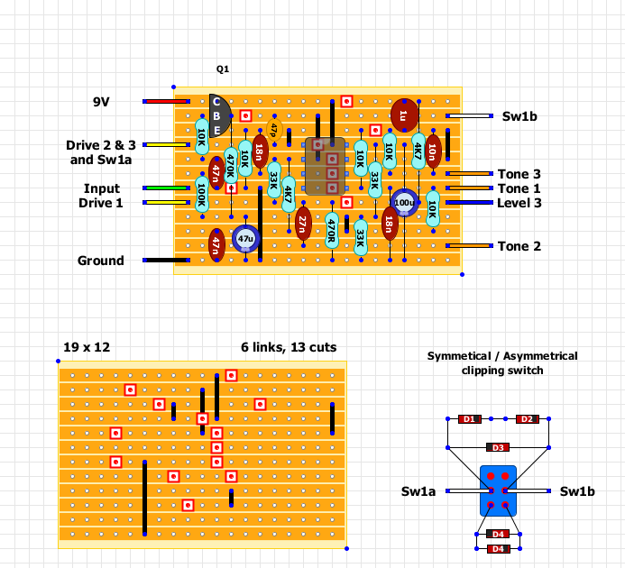
 
I don’t understand...what’re you trying to accomplish? The linked layout already has a diode clipping switch. You solder the diodes directly to the lugs—no need for a daughter board.
 
How many different diode combinations do you need? If you’re experimenting just use a breadboard it’s much easier!
 
Can you show a pic of the other side? Is that vero or perf board?
That pedal is long gone, no other pics. Vero/Strip board.

One pad on the PCB goes to center lug of switch.
Other pad goes to both diodes.
Other end of each diode goes to the top or bottom of switch.
Keep in mind polarity of diodes and the PCB pads.
 
Thanks! Hoping I get a breadboard for Christmas. Been slowly building up my toolbox. Started vero a few weeks ago.
 
Back
Top