DIY Amp Switcher Brainstorm

Tomnyhc

New member
Hey y'all,

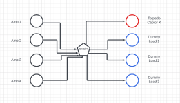
I'm currently recording using some low wattage tube amps through a Torpedo Captor X in my little home office/studio. What can be annoying about this is that I have 4 different heads I use and only 1 Captor. I'm trying to come up with a way to have all 4 heads plugged in and route 1 of the amps to the captor and the other 3 to dummy loads (as a precaution so that each amp is always seeing a load). I'm drawing a blank but would I be able to achieve this with a rotary switch? Worst case I would just wire inputs to outputs and label them but I would really prefer a solution where I would not need to plug/unplug anything but could just operate with a switch. Here's my crude diagram of what I'm picturing:

Otherwise, has anyone seen a better approach to a DIY amp/cab switcher?

screen-shot-2023-01-28-at-3-52-47-pm-png.41182
 

Attachments

  • Screen Shot 2023-01-28 at 3.52.47 PM.png
    Screen Shot 2023-01-28 at 3.52.47 PM.png
    48.9 KB · Views: 90
Last edited:
Can’t answer, but I have 3 concerns that may not be issues at all:

1. in a situation like this, can ground be treated as a constant? (So no need to switch grounds between anything. It seems like it should be, but the fact that they are amp outputs had me wondering)

2. these are amp outputs, so I’m not sure if most rotary switches are rated for this. Expect to spend a lot on one that is. (Sexy answer would be to use a rotary to control a series of relays…)

3. It also seems like you’d want switches that “make before break”
 
I was wondering about the make<break vs break>make, and as soon as you said it Alan it made sense for both which and why.

The relays-&-switch idea sounds good; I can't think of any DIY stuff that can handle that many amps and the only commercial thing I know of is Radial's amp switching stuff. Maybe we should put some Radial utility gear in the wish list...
 
I think it’s fair to assume that the speaker outputs do not share the same “ground”: I think since they are isolated outputs, there is no ground at all, just positive and negative connections.
 
I think it’s fair to assume that the speaker outputs do not share the same “ground”: I think since they are isolated outputs, there is no ground at all, just positive and negative connections.
This was how I thought it through also. So we end up with a rotary switch controlling relays that are each DPDT, and each configured so that the normally closed side is connected to the dummy loads (in case there’s a switch or power problem, the relays would all flop to the load position). The rotary switch only has to control the current going to the coil of each relay. The one complication I can think of, and it may not be an issue, is if there is a lag in the relay throw; if so, would there need to be a micro-controller that deals with the latch “timing gap?”
 
What I also can’t work through (at least this early in the west coast morning) is if you need a dedicated dummy load for each amp. I can’t picture it with n-1 loads. The N.O. Side of each relay would be connected to the Torpedo, but I think each relay needs its own dummy load to switch into. Unless there’s a way to do it with logic. (But that’s beyond my understanding.)
 
Back
Top