You are using an out of date browser. It may not display this or other websites correctly.
You should upgrade or use an alternative browser.
You should upgrade or use an alternative browser.
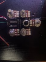
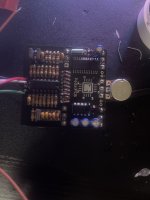
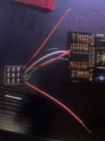
Does this PCB look ready to receive power?
- Thread starter azaheltorres05232007@gmai
- Start date
azaheltorres05232007@gmai
New member
Gave it power and the regulator seems to be working correctly (Giving ~3, 0, ~7 readings left to right), but the FV-1 at pin 28 is only reading ~1.7 volts, the led is always on but gets brighter when footswitch is in on position. What seems to be the problem? Thanks for your responseGive it a go!
Fama
Well-known member
The wires going to the footswitch seem kinda long and untrimmed on the other side, did you fix that after the pic or could they be making contact there?Gave it power and the regulator seems to be working correctly (Giving ~3, 0, ~7 readings left to right), but the FV-1 at pin 28 is only reading ~1.7 volts, the led is always on but gets brighter when footswitch is in on position. What seems to be the problem? Thanks for your response
Are the pots insulated from the PCB? I can only see one having insulation, could the others be shorting components?
Like Bricksnbeatles said, four of the pots are upside down, but they should still work, just in a funky manner.
azaheltorres05232007@gmai
New member
Why’d you put 4 of the pots upside down?
Thanks for the reply, the footswitch right now seems to be the issue, I checked my fv-1 again pin 6 and got 3.3V so that’s not the problem, pots have electrical tape so to prevent shorts. I’m thinking maybe there’s an issue with the breakout board and its signal path so i’m going to just wire it directly and see how that works. Thanks again!The wires going to the footswitch seem kinda long and untrimmed on the other side, did you fix that after the pic or could they be making contact there?
Are the pots insulated from the PCB? I can only see one having insulation, could the others be shorting components?
Like Bricksnbeatles said, four of the pots are upside down, but they should still work, just in a funky manner.
Fama
Well-known member
You didn't answer my question about the wires touching each other after they've gone through the breakout board?Thanks for the reply, the footswitch right now seems to be the issue, I checked my fv-1 again pin 6 and got 3.3V so that’s not the problem, pots have electrical tape so to prevent shorts. I’m thinking maybe there’s an issue with the breakout board and its signal path so i’m going to just wire it directly and see how that works. Thanks again!
I doubt it's the breakout board itself, but I have resolved weird issues like that by wiring directly too, there could be bridges or something. You could check that connectivity works as it should and doesn't do what it shouldn't with a multimeter if you have one handy, before reworking it? There's a risk of ruining the footswitch when desoldering.
I also once had an "always on LED" issue which was caused by one strand of wire making contact from the SW to GND, but you use solid core wire so it's not that (plus it wouldn't be brighter once you switch it on in that case).
azaheltorres05232007@gmai
New member
Oh right, the wires weren’t actually touching I had trimmed them off after I took that photo.You didn't answer my question about the wires touching each other after they've gone through the breakout board?
I doubt it's the breakout board itself, but I have resolved weird issues like that by wiring directly too, there could be bridges or something. You could check that connectivity works as it should and doesn't do what it shouldn't with a multimeter if you have one handy, before reworking it? There's a risk of ruining the footswitch when desoldering.
I also once had an "always on LED" issue which was caused by one strand of wire making contact from the SW to GND, but you use solid core wire so it's not that (plus it wouldn't be brighter once you switch it on in that case).
And I did notice that the led wire was bridging over to one of the switch through holes by a couple strands so I fixed that
But yeah i’m planning on just switching to wiring directly, ditching the breakout board, buying a couple more switches since it’s honestly gonna be a mess to desolder the one I have.
Thanks for the reply
Fama
Well-known member
Remember to check your input and output jacks to verify you've wired the ground and hot wires correctly, that's the one that still gets me from time to time.Oh right, the wires weren’t actually touching I had trimmed them off after I took that photo.
And I did notice that the led wire was bridging over to one of the switch through holes by a couple strands so I fixed that
But yeah i’m planning on just switching to wiring directly, ditching the breakout board, buying a couple more switches since it’s honestly gonna be a mess to desolder the one I have.
Thanks for the reply
I have a fair bit of experience with component lead ends piercing electrical tape easily. If that is all that is on your pots assume they are not insulated unless you have made it really really thick (like thick enough that even if the longest cut lead end went in as deep as it possibly could then it wouldn't actually reach).
swelchy
Well-known member
PJS is absolutely correct..... electrical tape will not protect... leads poke through that pretty easy and will cause you tones of troubleshooting grief.... at the least id throw some thin plastic under there.. ideally pot covers though... I have 3d printed versions listed on thingiverse if you happen to have a 3d printer to print them out.I have a fair bit of experience with component lead ends piercing electrical tape easily. If that is all that is on your pots assume they are not insulated unless you have made it really really thick (like thick enough that even if the longest cut lead end went in as deep as it possibly could then it wouldn't actually reach).
If the ones you designed are the ones I just printed then thank you very much. I printed some for dual gang pots and they are awesome.PJS is absolutely correct..... electrical tape will not protect... leads poke through that pretty easy and will cause you tones of troubleshooting grief.... at the least id throw some thin plastic under there.. ideally pot covers though... I have 3d printed versions listed on thingiverse if you happen to have a 3d printer to print them out.
giovanni
Well-known member
To @Bricksnbeatles point, your pot being upside down may create weird controls. And definitely won’t fit the drill template.
Not sure if it's clear, but there should be two rows of three knobs. So that lonely pot sticking out the top should have one each side of it. The rotary switch should have the lower two pots either side of it. That's what we mean when we ask about four of the pots being upside down.
andrewsrea
Well-known member
Fire it up and let out the magic smoke!
(just kdding)
(just kdding)
swelchy
Well-known member
if the user was swelchy they are mine.... Which I think I'm the only one who has them posted on thingiverse.If the ones you designed are the ones I just printed then thank you very much. I printed some for dual gang pots and they are awesome.
falco_femoralis
Well-known member
With the pots turned around like that they will behave in the opposite of normal - ie turning clockwise will reduce the effect. They are meant to all be positioned like the center top one. You should try and use some desoldering wick and remove them, but go slowly and carefully. It's ok if it takes 20 minutes, just don't overheat the board or pry too hard or you will break a solder pad.
Also, elec tape is not enough to shield the backs of the pots from the component legs on the back of the board. You need to use the plastic dust caps.
Also, you are missing the bypass LED and the component legs can be trimmed much shorter.
Also, elec tape is not enough to shield the backs of the pots from the component legs on the back of the board. You need to use the plastic dust caps.
Also, you are missing the bypass LED and the component legs can be trimmed much shorter.


