metalguy55
Member
Any tips on combining two pedals in one enclosure or a document to explain how to hook them up?
PedalPCB has you covered: https://www.pedalpcb.com/product/3pdt-order-switch/

Oh, yea, I seeBro...You add another foot switch. If you want to change the order of effects you just step on the switch.
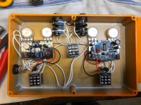
Your In & Out jacks are insulated so there is no Ground between PCB's or Enclosure.I am have just finished wiring up a muroidea and percolation station. I am getting nothing. LEDs work. No sound with or without pedals engaged.
How should I wire the negative wires on the input and output jacks? Is this my problem? It is not clear on the wiring diagram to me.
View attachment 9204

Could I also just change the jacks back to the standard metal jacks?Your In & Out jacks are insulated so there is no Ground between PCB's or Enclosure.
Attach a Wire between Ground terminals on In & Out jacks as pictured!
Because of the Plastic Jacks, you need both Footstwitches to be Grounded to stop interference.
Solder a wire to the Serrated metal washer that comes with the Footswitches & attach the other end to Ground on each PCB.
View attachment 9206
That would be the best option.Could I also just change the jacks back to the standard metal jacks?
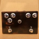
Success. Since I wanted to keep moving on this thing, I switched the jacks out, and instant success. Percolation Station into a Rat for "taming" with order switch option. Totally gnarly and satisfying! My attempt at doing a nice finish failed so I ended up sanding it down. Now it looks like a cheeseball "relic'ed/road worn" pedal, but oh well.That would be the best option.
Remove Paint from Inside enclosure where In & Out jacks make contact.
NOTE : Have you tested the individual PCB's are working correctly.
If you have GROUND connection from Power jack to both PCB's, you have a problem elsewhere, the plastic jacks will only cause you to have some background noise.
Try putting a Ground wire between the 2 plastic jacks to see if it fires up.
If not, you definately have a problem elsewhere.

