This issue might be similar to:
 forum.pedalpcb.com
forum.pedalpcb.com
forum.pedalpcb.com
I assembled the Duck Box Pedal and it is now in a functioning state ("Does something" when turned on - no unexpected behaviour when in Bypass). Nevertheless, most of the time the filter frequency seems to be stuck in a position at the lower end of the frequency range(muffled sound).
Interesting though is that when the guitar's strings are being struck rather hard the filter begins to move, always driving the level so hard that some nasty clipping occurs..
Somehow the actual "envelope following" seems to be off as far as I can make assumptions. It seems to me that the sensitivity of the envelope detection is both too sensitive and not sensitive enough at the same time.
I measured the ICs pins while having the pedal on power supply:
IC1 --- 1 - 4.24V --- 2 - 4.24V --- 3 - 2.85V --- 4 - 0V --- 5 - 4.1V --- 6 - 4.16V --- 7 - 4.14V --- 8 - 8.33V
IC2 --- 1 - 3.62V --- 2 - 2.02V --- 3 - 4.08V --- 4 - 0V --- 5 - 4.08V --- 6 - 4.16V --- 7 - 4.08V --- 8 - 8.33V
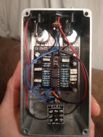
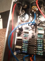
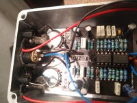
Also enclosed are some, hopefully not too blurry, pictures of the pedal's interior.
I hope that it is enough info to create some suggestions and would love to hear them!")
Duck box doesn’t quack
So I finally had a chance to test this guy out this morning, but I didn’t get any sound :( after opening it up I realized I put IC1 in the socket wrong. The two bottom legs were sticking out of the socket. After fixing that(I put a whole new 4558 in because the legs got bent) I got sound. But...
SOLVED - Duck Box Help!!
Hi, I am on my second attempt at a Duck Box. This is my 5th or so pedal build. But for some reason I can't get it working. I have signal, the footswitch is working, the LED is working. The Toggle seems to be working. When you move positions it changes the sound. But neither knobs work and it...
I assembled the Duck Box Pedal and it is now in a functioning state ("Does something" when turned on - no unexpected behaviour when in Bypass). Nevertheless, most of the time the filter frequency seems to be stuck in a position at the lower end of the frequency range(muffled sound).
Interesting though is that when the guitar's strings are being struck rather hard the filter begins to move, always driving the level so hard that some nasty clipping occurs..
Somehow the actual "envelope following" seems to be off as far as I can make assumptions. It seems to me that the sensitivity of the envelope detection is both too sensitive and not sensitive enough at the same time.
I measured the ICs pins while having the pedal on power supply:
IC1 --- 1 - 4.24V --- 2 - 4.24V --- 3 - 2.85V --- 4 - 0V --- 5 - 4.1V --- 6 - 4.16V --- 7 - 4.14V --- 8 - 8.33V
IC2 --- 1 - 3.62V --- 2 - 2.02V --- 3 - 4.08V --- 4 - 0V --- 5 - 4.08V --- 6 - 4.16V --- 7 - 4.08V --- 8 - 8.33V
Also enclosed are some, hopefully not too blurry, pictures of the pedal's interior.
I hope that it is enough info to create some suggestions and would love to hear them!