Dumbloid special on stripboard

pi.cast

Active member
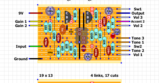
I really wanted to build my first stripboard circuit, so I decided to go for the Shin's Music Dumbloid special, using Tagboard effects layout.


As for many others of my build, I choose to clone the original pedal cosmetically:

IMG_8319.JPEG

IMG_8320.JPEG

IMG_8316.JPEG

The circuit came out great I think, apart from the 1uF electrolytic that was really too big to fit. The offboard wiring is really a rat's nest. I need to get better at routing all these wires.
Overall the sound doesn't convince me 100%, regardless of the hype behind this pedal. And I don't think it is related to my build, as a friend of mine owns the original pedal and it sounds exactly the same. In some circumstances, it's a great overdrive, but more often than not it sounds quite fizzy and harsh.

I'll experiment with some clipping diodes I think.
Meanwhile, I will definitely build more stripboard circuits as it was a lot of fun.
 
I really like Vero - it's a lot more forgiving of component swaps than PCB. BTW you can get smaller 1µF caps from Tayda - the 63V red Wima caps fit much more easily. Although one small complaint I often have with those tagboard FX layouts is that whoever designs them often doesn't take into account to size of the component. Fair enough - they're not being paid for their work. But after you get the hang of Vero you start to make your own layouts which can suit you better - and for me that's half the fun.

Other things you can try with vero: sand the edges of the board smooth with a belt sander - Takes all of a minute and means less snagging of wires on the edges of the board. When attaching the wiring to the board cut the wire to length as soon as it's soldered to the board by placing the board where it will end up and pulling the wire to where it will end up. Cut at that point, allowing for a little bit at the end to strip and solder. That way you'll end up with a lot less spaghetti!

For longer wires, like the ground wires from jacks to switches, I like to run the wire around the inside corners of the enclosure. It looks neat and seems to hold the wire in place so it can't snag in an input jack or something. But in general the shorter a wire can be the better.

But you're off to a flying start and the box looks killer! Beware - it's addictive!
 
That rat's nest isn't as bad as you think. With stripboard I make sure, like you, to you use multi-colored wires. This helps for troubleshooting and knowing which pot does what.

Looking at the picture, I would move some of those wires away from the input jack. The plug may snag those wires unexpectedly.

Great job! I agree with @HamishR, it's addicting once you realize you don't need a PCB. I've probably got 2 dozen layouts complete waiting for an enclosure home.
 
I've seen inside a fair few Mad Professor pedals and they are stuffed full of wire! I suspect they might be using the wire as stuffing to stop the PCB from moving around. Such a mess.
 
I really like Vero - it's a lot more forgiving of component swaps than PCB. BTW you can get smaller 1µF caps from Tayda - the 63V red Wima caps fit much more easily. Although one small complaint I often have with those tagboard FX layouts is that whoever designs them often doesn't take into account to size of the component. Fair enough - they're not being paid for their work. But after you get the hang of Vero you start to make your own layouts which can suit you better - and for me that's half the fun.

Other things you can try with vero: sand the edges of the board smooth with a belt sander - Takes all of a minute and means less snagging of wires on the edges of the board. When attaching the wiring to the board cut the wire to length as soon as it's soldered to the board by placing the board where it will end up and pulling the wire to where it will end up. Cut at that point, allowing for a little bit at the end to strip and solder. That way you'll end up with a lot less spaghetti!

For longer wires, like the ground wires from jacks to switches, I like to run the wire around the inside corners of the enclosure. It looks neat and seems to hold the wire in place so it can't snag in an input jack or something. But in general the shorter a wire can be the better.

But you're off to a flying start and the box looks killer! Beware - it's addictive!

Thanks for the suggestions! Really helpful!

Yes, I could have used a smaller cap, but a) I was keen on using only Panasonic capacitors (I'm obsessed with consistency :D), and b) didn't want to wait multiple weeks for just one missing cap.
I've actually sanded the edges of the veroboard and even beveled them, but next time I could probably be more aggressive.

I tried to be rational with the wire placing, by measuring the length of the leads in place one by one and cutting them accordingly.
However, what I've noticed is that the tagboard effects topology wasn't very suitable for the layout of the controls of the original pedal.
You had multiple wires crossing from left to right, so eventually, it ended up being a bit of a mess.

I think running the longer leads around the edges of the enclosure is another really good suggestion, I'll get some solid core wire for that.

By the way, I totally see how addicting this is and I will definitely build more in the future.
 
That rat's nest isn't as bad as you think. With stripboard I make sure, like you, to you use multi-colored wires. This helps for troubleshooting and knowing which pot does what.

Looking at the picture, I would move some of those wires away from the input jack. The plug may snag those wires unexpectedly.

Great job! I agree with @HamishR, it's addicting once you realize you don't need a PCB. I've probably got 2 dozen layouts complete waiting for an enclosure home.

Thanks!
You are right, I've actually moved the wires away from the input jack after reading your suggestion!
 
I've seen inside a fair few Mad Professor pedals and they are stuffed full of wire! I suspect they might be using the wire as stuffing to stop the PCB from moving around. Such a mess.

To be fair, even the original dumbloid is a wiring mess on its own.
 
Oh I don't think yours is a mess! I've seen heaps worse, even in "professional" builds.

And yeah, that's kinda what I mean about those tagboard layouts. I really enjoy the masochistic chore of drawing my own layouts. I like to try to get all the gain pot wires up top left, the volume 3 wire top right, tones on the side that they will attach to, etc. Some circuits are easier to line everything up than others.

For examle this one worked out well:

Angry Charlie mod.png

And was relatively easy to get everything close to the pots they will attach too. Sometimes I'll start from scratch when I don't like a layout.

Bluesbreaker.png

The Bluesbreaker was a bit of a bugger but I'm happy with how it turned out. I couldn't quite get my volume wires where I wanted them but it worked out ok because there are only three knobs to negotiate with the wiring. And you can see how I like to leave room for potentially large electrolytics. You have to watch out when spacing box caps across two rows rather than three - You can see at the top left on the Angry Charlie there is a 1nF cap across two rows which is fine, but it still needs three rows of space. I try as hard as I can to limit electrolytics to two row spacing, box caps the 3 rows and ceramics to three rows, but it's tricky and almost impossible sometimes without making things more complicated than necessary. BTW these layouts are for my own use and sometimes aren't exactly like the originals.
 
@HamishR those are really nice layouts! I definitely need to take more time to sharpen my stripboard design skills. I see where you're going with trying to keep it clean, but IMO as long as there's no noise generated from "crossing the streams" I really don't care what it looks like underneath if I'm building it for myself after it's all boxed up since I won't see it. Sometimes I enjoy the challenge of the rat's nest.
 
Back
Top