SOLVED First build excitement, and then reality hits.

Dan0h

Well-known member
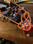
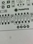
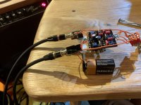
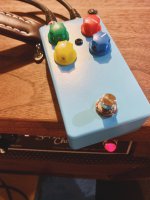
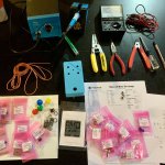
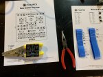
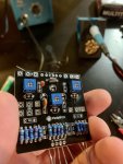
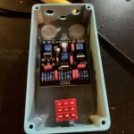
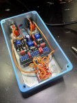
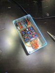
I assembled my first pedal yesterday, SOB. The DC jack I ordered didn’t line up right so I decided to use a 9v battery clip instead until I could get a proper DC jack. When finished I plugged in my guitar, hooked up a battery and plugged into the amp - everything worked, got sound, bypass is good. Hit the button and the led came on but no sound. Tweaked the trim pots hoping that would start some sound. Fiddled around for a few minutes and then the Led went out and I realized the 9v battery was getting pretty Hot. Googled that, sounds like a short somewhere. Any suggestions on where to start? I don’t have a DMM only an old school Multimeter from RadioShack. Could I have damaged any of the components in this process? How can I check the J201s? Pretty bummed to say the least. But I am thinking this is part of the learning curve. I do not see any solder blobs causing shorts. Not really sure what could be shorting.
 

Attachments

  • 247B50BA-E7D7-4540-AA0C-B440DCF453E5.jpeg
    247B50BA-E7D7-4540-AA0C-B440DCF453E5.jpeg
    2.3 MB · Views: 36
  • F6BD6356-FCA9-412F-ACA3-021FD7EEFD17.jpeg
    F6BD6356-FCA9-412F-ACA3-021FD7EEFD17.jpeg
    2.7 MB · Views: 40
  • DCFB5AF5-9B4B-46DA-B1AC-FFB91C69BBC7.jpeg
    DCFB5AF5-9B4B-46DA-B1AC-FFB91C69BBC7.jpeg
    3.5 MB · Views: 43
  • 07168BCF-4A70-44F5-BC21-08E270ECFFEA.jpeg
    07168BCF-4A70-44F5-BC21-08E270ECFFEA.jpeg
    2.7 MB · Views: 52
  • EA40BB7A-B6CD-486B-A429-1E3339F9AB34.jpeg
    EA40BB7A-B6CD-486B-A429-1E3339F9AB34.jpeg
    3.4 MB · Views: 55
  • 5AC563F3-564A-4521-8551-44D9C2F5E541.jpeg
    5AC563F3-564A-4521-8551-44D9C2F5E541.jpeg
    2.2 MB · Views: 54
The J201s wouldn't cause a dead short so don't worry about those.

The dual pot (Bass) is probably touching the back of the PCB. It needs to be insulated well.
 
The J201s wouldn't cause a dead short so don't worry about those.

The dual pot (Bass) is probably touching the back of the PCB. It needs to be insulated well.
Thanks for the speedy reply.
I did put a square of black tape behind it because it was touching. Maybe something poked through the tape. I will try to swap one of the top pot dust covers to the dual one.
 
Fwiw, our technique looks clean and those are clear photos, so thanks. The post I made for the workflow tips was that same pedal. Regarding the possible short here's a tip that that I do on all builds. Specifically figure 18 and 22 from here:
 
Fwiw, our technique looks clean and those are clear photos, so thanks. The post I made for the workflow tips was that same pedal. Regarding the possible short here's a tip that that I do on all builds. Specifically figure 18 and 22 from here:
God damn this is excellent. Wish I would have seen this before. Thank you!
 
Actually, on further inspection, you should definitely reflow some, if not all, your pot legs. They look a bit cold. My iron is set to around 750°F and I generally spend roughly 2 seconds on on each lug, sometimes more if I'm coming in at a weird angle. In practice, I always do one lug of one pot then move to another pot and do one more, hitting each pot, then cycle back to the first and repeat. Insurance against overheating.
 
Actually, on further inspection, you should definitely reflow some, if not all, your pot legs. They look a bit cold. My iron is set to around 750°F and I generally spend roughly 2 seconds on on each lug, sometimes more if I'm coming in at a weird angle. In practice, I always do one lug of one pot then move to another pot and do one more, hitting each pot, then cycle back to the first and repeat. Insurance against overheating.
Thanks. Will do. Those gave me the most issues as I didn’t want to heat them too long, and the result was pretty sloppy. I will use the boards next time around vs trying to wire all 9 legs.
 
523b1189757b7fb36e8b456b.jpg
 
I'm not sure where your short is - hard to tell from the photos. From my own experience I would recommend using much less wire and thinner wire. You're making it difficult for yourself by having so much mass around the switch. Wire should be almost as short as possible. A little flex is good but you don't want excess wire in there because (a) it can act like an antenna, (b) it can get caught in other parts causing shorts and (c) it makes trouble shooting more difficult.

And clean the soldering iron tip after every solder. It just means giving it a wipe on a damp sponge or whatever. Heat both surfaces to be soldered for a second or two before applying solder then remove the heat as soon as the solder has flowed. You want to fill the hole with no gaps but without excess.

Actually the places I find shorts most often with PCB builds is where parts like switches or sockets meet the enclosure. Sometimes screwing the lid on will short out the switch, or a socket lug will hit the side of the enclosure. Checking everything with a magnifying glass can help!
 
Thanks for the ideas. For sure going to employ a magnifier, and going to step down a gauge on future wire ups. This whole process has been just a jump in the fire. Looking forward to finding the problem and fixing it.
 
Alright dudes. Finally was able to spend a few hours troubleshooting this build. I inadvertently got half the pedal to work... I jumped R1 and R9 (I circled where I jumped, not sure if those are 1 or 2 on the diagram) and everything after R9 worked. Volume and treble. No bass control so my Strat sounded super thick which is kind of cool but I’m missing the Gain section which is the whole point of this pedal. I went through and am getting voltage reading off everything except the bass pot, could I have gotten a bad pot? Or fried it with my noob soldering skills? And if it is a bad pot why would it take down everything before R9? Also, I couldn’t get any reading V or Ohms on R6. So I pulled it and put in a new 470k, still no reading, but I get voltage after R6 so it must be working?
Any ideas would be beyond appreciated. I’m thinking it might just be easier to order a new board and start again. This is a very humbling 1st try at something.
 

Attachments

  • F8732D96-9C4F-42DA-A2B8-16794F3A4356.jpeg
    F8732D96-9C4F-42DA-A2B8-16794F3A4356.jpeg
    1.9 MB · Views: 13
  • 6A946FFE-8B08-4B5C-8869-DCF926EC1625.jpeg
    6A946FFE-8B08-4B5C-8869-DCF926EC1625.jpeg
    2.8 MB · Views: 13
Alright dudes. Finally was able to spend a few hours troubleshooting this build. I inadvertently got half the pedal to work... I jumped R1 and R9 (I circled where I jumped, not sure if those are 1 or 2 on the diagram) and everything after R9 worked. Volume and treble. No bass control so my Strat sounded super thick which is kind of cool but I’m missing the Gain section which is the whole point of this pedal. I went through and am getting voltage reading off everything except the bass pot, could I have gotten a bad pot? Or fried it with my noob soldering skills? And if it is a bad pot why would it take down everything before R9? Also, I couldn’t get any reading V or Ohms on R6. So I pulled it and put in a new 470k, still no reading, but I get voltage after R6 so it must be working?
Any ideas would be beyond appreciated. I’m thinking it might just be easier to order a new board and start again. This is a very humbling 1st try at something.

Don't give up just yet!!! By jumpering R1 to R9 you know that the back half of the circuit is working, so you're halfway there!

As far as not having voltage on the Bass Pot, you should not have a DC voltage on it. There is only the wet AC signal from Q1 when the circuit is working. To check the bass pot check the resistance from R6 pin 2 and the Drive pot pin 3. Start with pot fully CCW, should be about 2M ohms, then slowly rotate pot CW and resistance should go down. If the resistance goes down the pot is good. If not, then check pot directly by measuring resistance from bottom row pin2 and pin1, rotate pot and check for change, then measure between bottom row pin 2 and pin 3 and rotate and look for resistance change. Next perform same test on top row of pot. If the pot checks out here but not between R6 and Drive pot, then you have a solder issue or a bad trace. If one of the checks directly on the pot is bad then replace pot.

Now I have to ask the obvious easy question. On the schematic in the build doc, it has you set the Trim pots, T1 to 2K and T2 and T3 so that there is 4.0Vdc on on Q2 and Q3 drains respectfully. You did do this step, correct. If not then do this and see if it works. If the pots are not set correctly they may prevent their FET from operating correctly.

Let us know what you find and we can go from there. Once you troubleshoot a few pedals it gets easier!
 
Last edited:
I can not thank you guys enough. This pedal sounds amazing!!
Issues found, thanks to your suggestions, and resolved. Trim 1, Q1, and Drive pot all had at least one pin each with noob solder. Once I reflowed correctly and lifted the bass pot up a tad, she gnarled like a beehive covered in moss. Just the subtle rasp I was looking for.

It’s pretty sloppy but a worthwhile first build. I’m not going to replace the blown Led or put in a DC jack. Instead, when these boards are back in stock I’m going to build a solid one.

Cheers again for all the help.
??????
 

Attachments

  • 7D22BE2F-1B3A-424E-B80E-583EDDE601FB.jpeg
    7D22BE2F-1B3A-424E-B80E-583EDDE601FB.jpeg
    3.4 MB · Views: 14
  • 82A85AB7-E322-48CC-B876-D686CC53DC61.jpeg
    82A85AB7-E322-48CC-B876-D686CC53DC61.jpeg
    2.2 MB · Views: 13
Back
Top