
You are using an out of date browser. It may not display this or other websites correctly.
You should upgrade or use an alternative browser.
You should upgrade or use an alternative browser.
First build progress - Muroidea
- Thread starter Grubb
- Start date


Robert
Reverse Engineer
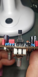
You'll probably want to leave the leads full length until you can test to be sure everything works properly. After that you can trim them down if
Once you're sure it works properly you might want to solder the transistor into the socket, they've been known to fall out.
Your soldering looks good, the square pad just above the "D" in "MUROIDEA" might need to be touched up, but otherwise I don't see any obvious problems.
Once you're sure it works properly you might want to solder the transistor into the socket, they've been known to fall out.
Your soldering looks good, the square pad just above the "D" in "MUROIDEA" might need to be touched up, but otherwise I don't see any obvious problems.
Chas Grant
Well-known member
WOW! That looks really good for a first time solder job. Good fillets, nice flow through and you cleaned the board! Keep it up!
BuddytheReow
Moderator
Agreed! My first build was a mess in hindsight, but I was patting myself on the back because it fired up the first time I plugged it in.WOW! That looks really good for a first time solder job. Good fillets, nice flow through and you cleaned the board! Keep it up!
Grubb
Well-known member
Thanks for the encouragement..I'm following the Basic Workflow Tips guide by @Jovi Bon Kenobi like it's my new religion, hence the clean boardWOW! That looks really good for a first time solder job. Good fillets, nice flow through and you cleaned the board! Keep it up!

Danbieranowski
Well-known member
A million times better than my first pedal!
Grubb
Well-known member
I'm going to hold off getting too excited until I try to fire it up. I wouldn't mind approximating your upwards trajectory though mate, you've got some nice builds under your belt.A million times better than my first pedal!
Danbieranowski
Well-known member
A lot of that is thanks to this community and just building a bunch. Check out the new Auditorium test kit for easy testing of your builds!I'm going to hold off getting too excited until I try to fire it up. I wouldn't mind approximating your upwards trajectory though mate, you've got some nice builds under your belt.
board here: https://www.pedalpcb.com/product/pcb365/
parts kit here:
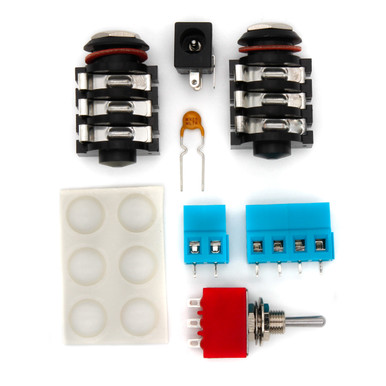
PedalPCB Auditorium Parts Kit
PedalPCB Auditorium Parts Kit - Stomp Box Parts - Pedal PCB
 stompboxparts.com
Your soldering looks great for your first time doing it. Nice work! Rat's are one of my favorite distortions, too. You're gonna dig it. Good decisionto socket the clipping diodes and chip for future swapping and experimenting.
The Auditorium is really great for testing stuff out before you commit to making a million more connections inside an enclosure. You can get that parts kit fo' free with code "AUDITORIUM" with a $25 purchase.
The Auditorium is really great for testing stuff out before you commit to making a million more connections inside an enclosure. You can get that parts kit fo' free with code "AUDITORIUM" with a $25 purchase.
Grubb
Well-known member
He tells me this the day after I order it (as part of an order well over $25)


Grubb
Well-known member
So I bought a drill press and have successfully bored out a hole on my Tayda pre-drilled enclosure that was too small for the LED bezel I had. So far so good.
I've just sat down to solder the footswitch into the breakout board. All of my connections look ok (to me) except the bottom right in this photo. Looks white on the outside. I've reflowed it a couple of times, it looks silver when hot but turns white again when it cools. Should I de-solder and try again?

I've just sat down to solder the footswitch into the breakout board. All of my connections look ok (to me) except the bottom right in this photo. Looks white on the outside. I've reflowed it a couple of times, it looks silver when hot but turns white again when it cools. Should I de-solder and try again?

Grubb
Well-known member
I ended up removing the solder and the next connection looked better. But now I have a worse problem I'm not sure how to solve. In starting to do the offboard wiring I was attaching the north end jack and power wires, when a small ball of solder flowed next door into the LED pad. I can't get my solder sucker close enough to the back of the hole to remove it because there's a pot really close. Is there another way to clear the hole? Help please!


BuddytheReow
Moderator
Use the solder sucker on the other side of the board. Just be careful not to overheat the board